• Please review our updated Terms and Rules here

Time to rebulid the pdp8/L

Not sure if this helps here:
When I worked in DEC Fieldservice and had to find a short in a 11/70 Backplane between two Signals
I connected a continuity beeper to one signal
Then I stacked two extender boards and runned the second probe slowly over the extender traces until it beeped
This had to be done for all suspected slots
So I could work out all connections to a specific signal and then look closely what wirewrap pin did cut through the insulation of a tense wire

Today you could eventually run some limited current through the suspect wire and use a thermal camera to see the path in a crowded backplane

For jumper wires: a female Berg connector pin crimped to a wire should do the job
 
Question: Does anyone make jumper wires for wire wraps anymore? Hm......
Adafruit, among others, have them in 3", 6", and 12" lengths, mainly for the RasPi, etc. experimenters.. (You might have to peel one off a set of 40.) The crimp pins to go over the header posts pins are also available, but the tooling to do the crimps properly is expensive and fussy.

It might be easier to just add another wire-wrap wire of your favorite color :).

As far as tracing the old wrap, I have an old "bug hound", which has a feature like that. I'd worry that the 9V battery could theoretically exceed the rating of the TTL (usually 7V max). (Possibly you could measure the output to see.)

Vince
 
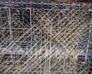
Well, I found something over by the A32-36 block that does not spark joy.....

smaller.jpg
 
I assume you are talking about the wire that looks burned from upper left to lower right.

That would not have smelled good when it happened.

Not the end of the world. It looks like a few other wires have been damaged as well.

I've seen this happen when someone was a little aggressive in making a corner and the edge of a pin will bite through the insulation.

I've also had it happen when I applied power and had a wire connecting 5V to GND. Miscounted pins on that one.
 
Yep, that's probably a power wire from the G series power control boards, and it goes right across where the rear A boards are. So this might be "part of the problem". It's also pretty far into the wiring loom back there so was probably an original DEC wire.

Time to document it and see about removing it. With it out I can see what kind of damage may have been done to nearby wires. I'm guessing enamel would work for re-insulating other wires.
 
Well hmm.... Took the wire out, it was burned badly and broken in at least one part. I marked the path with sharpie as I removed it in case I need to work on other wires.

But the odd thing is the nature of the wire: It goes from A28 B2 (the G785 main power card) down to B34 B2. However in the wiring maps I see:

A01B2 A01 B2
A28A B2

And that's it. Likewise for B34 I don't see anything on line B2. So is this another "custom thing" that probably blew up when some poor schmo plugged a normal posibus device into the system?

Edit: Still doesn't seem to work, back to drawing board.
 
Last edited:
Well, I'm puzzled.

As you say, I show a wire run from A28B2 to A01B2. This seemed like part of the -15V supply to the front panel, but now I don't think so.

The G785 drawing shows A28B2 to be the unregulated -15V power. B28B2 is the regulated -15V.
Connecting these together would likely toast the zener, then run with unregulated -15V.

The front panel drawing shows -15V on B2 of all four connectors. But then it makes no sense to connect AB2 to A28B2! It may make sense to connect A28B2 to the power switch, but the power switch wiriing isn't shown in the G921 drawings I have.

I also show no wire on B34B2. I'd expect that to be bussed to the regulated -15V supply, even though B34 doesn't need it.

It's possible that this wire was just part of the routing for -15V, and got burnt when someone shorted out the -15V sometime. If so, it was likely it was meant to go to B28B2, not A28B2.

Are you getting -15V? Not much uses it, so it might be broken. I think it should be bussed along B2 of each row (A, B, C, D).

Vince
 
Ok, stepping back a bit, I put the M707 card on the riser and took a good long look.

First I loaded up the simplest printing program there is, it reads the switch register, then sends it to the device, then loops until device says done, then loops. Well, we know the whole loops till done is broken, but does anything work?

Loaded it up, hooked up the 8 to my laptop with serial, then set address to zero, switches to 66 (Ascii 6) and hit the gas. Sure enough a "6" comes out on the laptop serial, which means:

1) The address decoders work
2) The flip flops in the 707 work for the shift register
3) It can actually print something
4) Well that's nice.
5) Still doesn't do skip for a damn.

Now, there is a flip flop on the 707 that signals done. It goes to a 7410 along with two other lines. The output of this is the SKIP signal. So let's look at the 7410 on the 707 board and see what's up.
Pins 9,10,11 are the three inputs to the NAND gate. With the program running 11 is high (device selected) which is good, 10 is high (output from the FLAG flip flop meaning the char was sent) which is good, but 9 is low, and is always low (never a pulse).

9 is called "I/O skip strobe" on the 707 docs, and IOP1 in the schematics. Ok, so what is on IOP1?

IOP1 AB30 AU2 Paper tape reader
AB31 AR2 Paper tape punch
B15 H1 Blank slot, probably parity
D02 F2-Our favorite inverter....
D31 H2--tty out
D32 D2--tty in

So my guess is it's coming from D02 which is the universal 7400 POS inverter. Since that signal is not changing, either D02 is bad (not likely as I swapped it from another unit), the line from D02 is shorted (possible), or whatever feeds that inverter is not working (also possible).

Time to research what drives IOP1.... If that's not working then the SKIP circuit will never enable and things will not work.
 
Time to research what drives IOP1.... If that's not working then the SKIP circuit will never enable and things will not work.
Well, that's easier. The idea is that every IOT instruction should send IOP1, IOP2, and/or IOP4, depending on MB11, MB10, and MB09, respectively. Which is to say, the last 3 bits of the instruction. So, TSF is 6041, the last digit is 1, so that instruction will generate (only) an IOP1.

Chronologically, IOP1 happens before IOP2, which happens before IOP4. They are gated versions of IOP_A, IOP_B, and IOP_C, which are generated by the 3 bit shift register implemented as one half of C06. (This is all on sheet 2 again.) The shift register is clocked by !IO_ROT, which is generated from the M310 at D07. (D07 also forms a short loop with D08, to allow !IO_ROT to repeat when needed.)

The whole thing should be kicked off by TP3 and IOT, and should end when IO_RECYCLE is inhibited by IOP_C.

Vince
 
IOP1 is generated when the 11 bit is set in an IOT. A 6041 or TSF is supposed to cause an IOP1. An IOP2 is set when bit 10 is set in the IOT instruction. n the case of the the console port this would be a 6042 or TCF instruction. The IOP4 is set when bit 9 is set in an IOT. An example of that is for the console would be a 6044 or TPC instruction. It is perfectly acceptable to combine bits where it makes sense. It does not make sense to combine the TSF with the others which is why it isn't done. It does make sense to combine the IOP2 and IOP4 and in the case of the console teleprinter instructions you get a 6046 or TLS instruction.
 
Well, this is weirder.

After checking the M310 at D07 I put C04 and D04 on the riser to see what was up. To do this I also had to pull the double width M700 in the slot forward. Not a biggie, got the riser in, the 700 in, and the cards in the riser.

Interesting. Looking at my notes I should have put the riser on C06/D06 (the M216) but instead I pulled C/D 04. I know this because I had to remove the M700 in order to get the riser in. Little mistakes like this get made from time to time, thank heavens I can edit this post for awhile.

Then I fired up the computer, ran the program, and all hell broke loose. The program ran off into wacky land, zeroing memory location 0, and doing all sorts of stuff in a nice light show

After this happened a few times I took out the riser and put C04 and D04 back in the backplane. Same issue. I toggled in a simple AC increment program to see if the computer had lost its mind, but that ran properly. Then I keyed in the program and single stepped it. The program is as follows.

0/7604
1/6046
2/6041
3/5002
4/5000

Previously the program was looping between 2 and 3, because the IO pulses weren't working. Now I saw instruction 2 execute followed by a jump to 5. Great, it's double skipping now.

To test this I put in a simple jump sled from memory locations 5-10 with jumps to 0 (5000). Fired the program at full speed and sure enough it prints rows of 6's when I had 66 in the switch register and other ASCII characters when I set the switches. So things are..... better-ish?

First question of course is why. The only thing that changed was pulling the C06/D06 cards and fitting them in a riser. Possible there is crap in the slot, I'll check. But more interesting is why is it double skipping, that's a new one as well.

I might want to try entering a simple skip on zero AC or skip on zero link to see if the whole skip system is broken or just the I/O skips. Tomorrow, but at least I have some progress and know that the I/O skip circuitry sort of works. Better than not working I suppose :)

Progress?
 
Last edited:
This is a lot of fun by the way.....

So this morning I figured I would check the operation of skip instructions in general. I did a quick test program awhile ago with a simple testing of a skip on link and it worked, so time to figure out what's going on.

To simplify things I will start by testing the simplest thing: The Link. That takes the whole IO system out of the picture which is helpful when trying to isolate stuff. So let's see if skips work....

Program 1: Simple skip.
Code:
300/7240    Sets AC to all ones.
301/7001    Increments AC, this will set the link bit.
302/7420    Skip if link set (yep)
303/7402    Halts (bad)
304/7402    Halts (good, skip worked)

This program works. It skips over 303 and stops on 304.

Now let's extend it a bit.
Code:
300/7240    Sets AC to all ones.
301/7001    Increments AC, this will set the link bit.
302/7420    Skip if link set (yep)
303/7402    Halts (bad)
304/7402    IAC (This will increment the accumulator, link still set)
305/7402    IAC (Do it again, why not)
306/7430    Skip Zero Link (should not skip as link is 1)
307/7240    Clears and Sets AC to all ones. (easy to spot, should execute)
310/7001    Increments AC, sets link to zero due to overflow
311/7430    Skip Zero Link (should do this)
312/7240    Do another clear and set AC
313/7402    Halt

Now when I run this, the first skip works properly and hops to 304. Likewise the instruction at 306 does not skip 307, which is good. However the Skip at 311 jumps to 314.....

What this seems to say is that the skip system has a problem:
The first time a successful skip is encountered it hops one instruction
If a skip check fails it goes to the next instruction
The second time a successful skip is encountered it hops TWO instructions.

This seems to match what I saw last night, I'm guessing the first character skipped properly but the second character sent the system two instructions up and missed the jump to beginning.

One other oddity: I wrote another program that skipped properly on the first Skip Link Set, but did not Skip on a second skip link set instruction right after the skip. Not sure if this is a bug or a pdp8 limitation but here is the code:

Code:
300/7240    Sets AC to all ones.
301/7001    Increments AC, this will set the link bit.
302/7420    Skip if link set (yep)
303/7402    Halts (bad)
304/7420    Skip if link set (Link is still set...)
305/7402    Halts (bad, halted here)
306/7001    IAC (would show that skip worked, it didn't)
307/7402    Halt (never gets here)

Interesting...... Hm.
 
Last edited:
This must be a stumper.... So I went back to the simple 5 line program to output characters to the serial port based on the switch register and did a video of it running single step. You can see that every time it jumps to location 6 instead of 5 on the skip. Why.....


And here is what it looks like on a normal system:

 
Last edited:
In the meantime while I let all this skip stuff sit I thought it would be a good time to figure out the broken M707 board. So I put it in this computer, and fired up the program. Sure enough it never hops over the skip instruction meaning that not skip works properly. However I do see a quick flash on my RS232 tester so something might have happened.

Hook up the computer, set serial to 300,8,n,2 and sure enough when I run the program with 66 in the switch register I get a "6" output. Just one, but that means something is working.

So what works on the 707, and what doesn't.

Well, device select works, as does the 8 flip flops for the data word, the clocking, the shift register, and the stop bit generators. What's not working is skip, which could either be the FLAG flip flop or E13, which is the 3 input NAND driver for the IO Skip signal. Given the number of bad NAND gates I have found that are drivers for other chips I think I'll replace E13 first and see if it starts working.

If not I'll move into the Flag flip flop and see what's happening there.
 
So the 707 repairs have been going on. First I pulled the 7410 at E13 and tested it. Sure enough it's good, that's not the problem. Then I tried swapping the flip flop E16 to see if that did it. Nope.

Enough swapping parts. I walked through what happens with a good board and a bad board. It's tough, if you run the program the good board does a lot (because of course it's skipping properly) and the bad board isn't, but I very quickly figured out that the E13 gate is not being tripped due to the flip flop at E16.

And the flip flop at E16 has the D set on it from the NAND gate at E9 which seems to be taking the inputs from the 8 flop flops that make up the character. On a good board when I look at say pin 2 on E9 I see a little chirp each time a character is sent (including the first time when you start). And then on E8 you see a chirp as well (character transmitted I supposed) On the bad board you see the chirp on pin 2, but pin 8 never chirps or changes state. Therefore I think this gate is bad.

Ordered a couple of 7430's, I'm out of them and have had those fail on other boards. Will see in a few weeks if the 707 board works. Meantime any thoughts on the double skipping that this thing does (I'm programming around it for now but it's still really broke)

C
 
Meantime any thoughts on the double skipping that this thing does (I'm programming around it for now but it's still really broke)
I freed up a little time to try to come back up to speed here. So far, what I think I know is that the SKIP FF output works by enabling a CARRY_INSERT if the PC_ENABLE is set (routing the PC to tha adder) and a skip is enabled.

The actual update of PC is triggered by PC_LOAD, as created by A13 and B08.
The triggers are any of:
Code:
        Instruction FETCH
        JMS execute cycle
        JMP direct
        JMP indirect defer cycle
        Load Address
        SET_IO_ON
where SET_IO_ON is strobed at the beginning of an I/O instruction.

It is also meant to be the case that PC_LOAD resets SKIP, so that each skip occurs just once.

I believe the other adder operand should always be wither 0000 or 0001 (in the FETCH case, for example).

For a skip OPR to skip multiple, the PC_LOAD might be glitchy in a way that isn't always seen at the reset input of the skip FF. Or maybe somehow the 0000/0001 assumption is violated (though that I think would lead to non-skip malfunction, too). If I am understaning the group 2 skips, they just generate a carry-in at the next FETCH, so it's hard to see how they can skip more than once.

IOTs could skip more than once (up to 3 times) if they generated extra IOP pulses.

Hope that helps.

Vince
 
Hm. Ok. Well I thought that there might be a problem with C14 as that M113 does turn the PC_LOAD into a reset of the flip flop. But swapping that M113 with a known good one produces the same result: Instead of skipping one instruction on the IOT it skips three at a time.

It's not the M707, that is a known good and works with another system. So why would the M707 generate 3 IOP pulses on one system but only a single one on the other? Noise on the IO/Skip line perhaps going into A13? I've swapped A13 numerous times with the same results.

I wish the 8/L had the single step option instead of single instruction: I'd really like to know why it's doing 3 adds here to the PC instead of one.
 
Possibly. I have a dual channel scope and may be pulling it out before the day is done. Got a link to a good analyzer on Ebay?

Meantime the computer is in screwed up land with an intermittent fault. Every once in awhile when I power it up it goes crazy. As in hitting load address increments the MA, nothing works, etc. So either a loose wire or a intermittent component. I'll start troubleshooting this. But then it goes away and the computer goes back to the normal levels of "not working".

Hm. Well at least I have one good 8/L to work/test with.
 
In the meantime I finally got some new 7430's for the M707 module. When last we wrote on this problem, the M707 wasn't causing any skips, and the problem seemed to be in E9: Specifically no matter what the input signals the output signal was always the same. So it was broken.

Pulled it and replaced it with a new chip. Now things are a bit different: The 7430 gets its inputs from the 8 flip flops that store the character to be transmitted, and as each is read/strobed they're supposed to change state. When all have been set the 7430 transitions and sets the FLAG flip flop which should allow IO Skip to finally be transmitted.

Still doesn't work, and I'm going to need to think about it. The 7430 is changing state on its output but oddly enough when at rest a good 707 shows the inputs from the flip flops to be high with the output low. But with the bad 707 in place all the inputs are low with the output high at rest.

Hm. Getting closer. May just be the nature of different brands of flip flops or something else.
 
Back
Top