cosam,
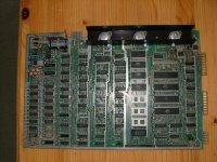
The 74LS244 has the PCB ref "U111" in front of it.
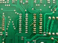
I have not looked at any schematics but I did notice that a few of the pins on this 74LS244 appear (on the underside) to be soldered together. Is this correct?
(I have ordered a 74LS244, hopefully the correct type, just in case I needed to replace it.)
Yes I have a digital ohm meter, should I be looking to check that each of the IC pins are connected to the circuit board (checking for dry/broken joints) or should I be checking for something more complicated?
Thanks,
David
The 74LS244 has the PCB ref "U111" in front of it.
I have not looked at any schematics but I did notice that a few of the pins on this 74LS244 appear (on the underside) to be soldered together. Is this correct?
(I have ordered a 74LS244, hopefully the correct type, just in case I needed to replace it.)
Yes I have a digital ohm meter, should I be looking to check that each of the IC pins are connected to the circuit board (checking for dry/broken joints) or should I be checking for something more complicated?
Thanks,
David