• Please review our updated Terms and Rules here

IBM 5154 Troubleshooting

Nicole,
Now, you won't be able to use that monitor!! You have put so much work into fixing it, you need it to be fenced off, like in a museum :cool:
DO NOT TOUCH the sign reads
 
I'd really suspect the pcb around the transformer now, it's really rare for the heater winding to go, as it's thick wire. get your meter out and do some continuity testing through the whole of the heater circuit, probably (carefully!) unpluging the tube base board from the tube to break the "circle" of the circuit.

I think your determination so far has been incredible, Well done so far!
 
heater

heater

Floppies_only said...instead of trying something that you aren't sure of to try to fix it
That's how you learn. Besides, somewhere in the thread it was suggested that if the heater winding proves to be shot, then at least you can take a stab at putting together a PWS for the heater.

Feeding high-frequency to the heater gains you nothing. It's just cheaper that way. Actually, because the heater is so close to the cathode, you don't really want anything in there that isn't part of the cathode signal. Some stuff you can get away with due to the persistence of the phosphor, though. (Look at the cathode signal of a color NTSC signal in an old B/W set)

nige the hippy said...it's really rare for the heater winding to go, as it's thick wire
You're absolutely right, nige. Unfortunately, since the wire is so thick, the joint between the wire and the pin at the base of the flyback can be somewhat sensitive to shock.
That's often the cause of transformers opening up as well, it's not the windings( unless there's a non-resettable thermal fuse in there), it's the connection from the windings to the pins. If it's a short, it's the windings. An open, it's usually a connection of sorts.

For tubes, DC heating is actually the least stressful. If you're paranoid about tube circuitry, you actually use a circuit that ramps up heater voltage gradually, and then cuts in anode & grid voltages. Or you run the heater a bit under spec. Or... , Well, I guess I should try not to get too side-tracked...

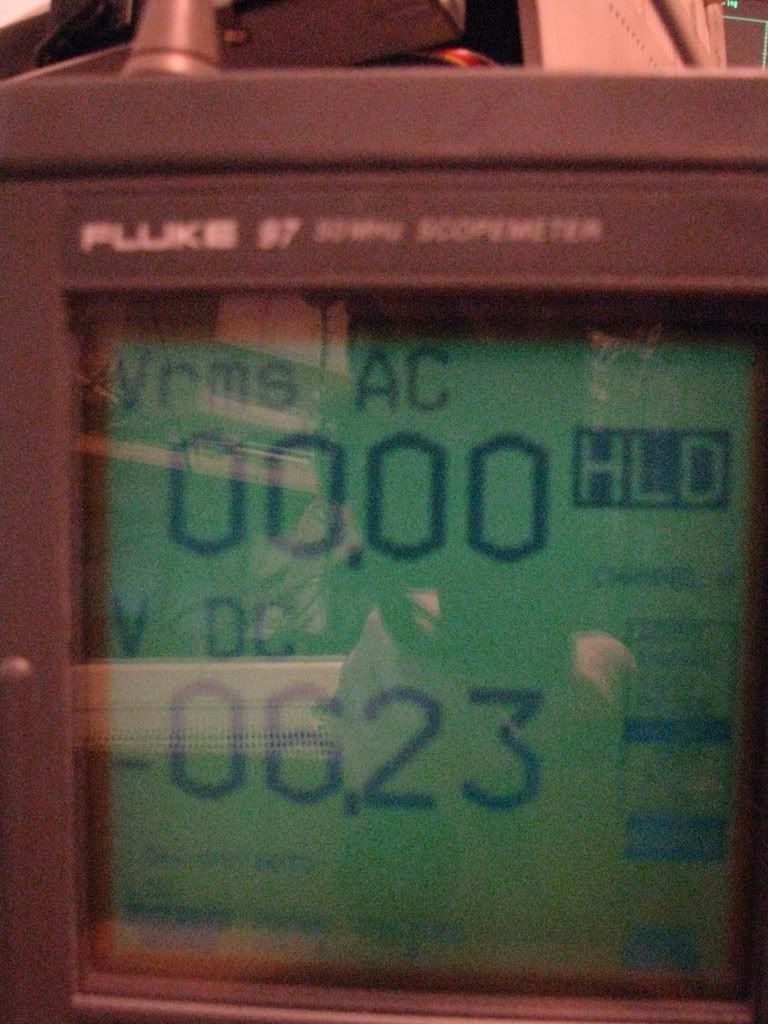
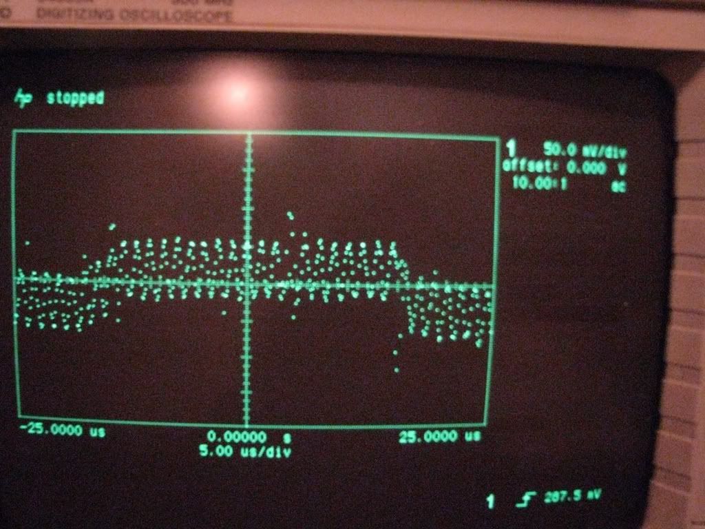
I'll be pulling a 5154 apart this weekend and will post the voltages, and maybe even a waveform or two.

Good job on improvising the heater PSU, by the way.

Oh, before I post, the lack of sharpness might also be a focusing problem, did you check that ?

patscc
 
OK this is what I´ve thought.

But the PSU is so weak...... (please remember that it broke in 3 pieces and I don´t want to open it every 2 weeks).

I think it is much easier to power the heater with a 2nd self-made PSU. I´ve already bought a 240V to 9V print-style transformer, this is connected to four 1N4006 in series to lower the voltage (OK, not so nice but works) and to a MAX1709.

Now I power the heater with a nice 5.5V high frequency voltage (I think this will be gentle to the cathode) and the picture is sharp. But how can I play with the focus?

Because an original 240V PSU won´t be available, I will replace the whole board with a self-made PSU the next time the 5154 will stop working. The actual one was a nightmare to repair.

I think old components such as cars, trains, computers or else are useless if they are not working and/or stored in a museum. I find that very boring.
My XT-286 has an (E)prom / Biprom-Programming job to do and is used every day. The comp is not in my house to entertain itself :)

Nicole,

Once I asked a woman in the Grafenvoer Post Exchange where she was from. "Aachen", she replied - and it sounded so beautiful.

Can't you ask somebody who worked on monitors how to go about fixing yours, instead of trying something that you aren't sure of to try to fix it?

Sean

Hi Sean,
that´s always a problem. Imagine that I´ve repaired the PSU myself (without the exchange of all components), connected a new CRT tube with different layout myself (everything without schematics but with my scope) and wasn´t always 100% sure but close to. I know that I couldn´t repair the moni without the experience of nige and patscc, but I thought the heating should be a very small problem to solve compared to the work I´ve already done.. Yesterday evening I thought about the heating circuit and was sure, that I couldn´t destroy anything with an AC or DC voltage under 6V. so I´ve tried it.

By the way was the girl nice or just the city´s name?? :) :) :)
Aachen is not so big, but has some nice old buildings (and quite a lot have been rebuilt after WW2, compared to other cities in Germany.) If you are in Aachen you can feel that the city is very old. The best thing is that the border to both the Netherlands and Belgium is only about 5-10km away and I love to buy food there or just ride through all 3 countries with my bike in less than 10 minutes...
 
Last edited:
nice

nice

Nicole said...1N4006 in series to lower the voltage (OK, not so nice but works) and to a MAX1709
What's not nice about it ?
However, there's one thing I don't understand:
9 VAC ~ 12.7 VDC no load.
MAX1709 Vinmax 5 VDC
Drop across 4 1N4006's, 2.4 VDC.

Does the 220~9 VAC transformer have a tapped secondary, so you're actually using 4.5 VAC ?

patscc
 
readings at heater

readings at heater

Sorry about the delay, had a touch of the flu.
The heater voltage on mine, after a 2 minute warmup is 6.23 VDC.
There's a negligible amount of AC ripple, so for all practical purposes a DC heater signal is fine.
Attached is a AC/DC meter reading (sorry about the glare) and a snap of the ripple waveform. (Quite low, actually)
8153_Heater_Voltage.jpg

8153_Heater_Waveform.jpg

patscc
 
Hi!

I've also got an IBM 5154 monitor which isn't working. Well, it starts up, and the green power-on LED light up, and a normal high-frequency noise is heard. But when I start the PC with monitor connected, the high-freq noise disappears, and I get no picture. I turn off the PC, and the high-freq noise comes back. What is the fault? I opened up the PSU part and had a look. There are two resistors (R32 and R37) which are connected in parallel, they are black and burned, and I can't see what values they are. I then had a look at the schematics posted earlier in this thread, but it doesn't seem to be the same as mine? What values are those resistors?
I've replaced the three capacitors C11, C13 and C14.

:EDIT:
And I'm living in Sweden, so we have got 220 volts in the outlet. Maybe my PSU is built another way than yours?
 
Make sure your monitor is FROM Sweden and not elsewhere, otherwise the reason it's not working could be that 220 volts.
 
I am completely sure that the monitor is from Sweden, and that it's made to handle 220 volts.

I've got a question about the screen. It has some kind of filter or something, or fabric over the screen. What is that? I don't want it there. :)
 
Last edited:
There are two resistors (R32 and R37) which are connected in parallel, they are black and burned, and I can't see what values they are. I then had a look at the schematics posted earlier in this thread, but it doesn't seem to be the same as mine? What values are those resistors?
1.2 ohms +/- 5% (brown/red/gold/gold)
Yes, both wired in parallel. I measured 0.7 ohms over them (close to expected).
 
I've got a question about the screen. It has some kind of filter or something, or fabric over the screen. What is that? I don't want it there. :)

That would probably be an anti-glare screen, which you can just pull off. There's a rubber ring around the outside of it, between its plastic and the plastic of the monitor case, which keeps it in place.
Pull it off, and then sell it on Ebay for the usual $ 5.
 
Well, I didn't find two 1.2 ohm resistors at my spare box. But will two 1.0 ohm resistors work instead?

Oh, and I removed the "anti-glare" thing from the screen. It's in very bad condition, small holes here and there, so I threw it in the trash. =)
 
By the way was the girl nice or just the city´s name?? :) :) :)
Aachen is not so big, but has some nice old buildings (and quite a lot have been rebuilt after WW2, compared to other cities in Germany.) If you are in Aachen you can feel that the city is very old. The best thing is that the border to both the Netherlands and Belgium is only about 5-10km away and I love to buy food there or just ride through all 3 countries with my bike in less than 10 minutes...

Funny guy :)
I live in Sittard, and go shopping in Germany because I love to buy food there :D

There is by the way a nice shop here that did a nice job in repairing my 5154...

(for other viewers- that just on the other side of that border)
 
Well, I didn't find two 1.2 ohm resistors at my spare box. But will two 1.0 ohm resistors work instead?
Without doing some calculations/investigation I would say that 1 ohm would be okay for a short test only. Remember, they are half watt.

I traced out this part of the circuitry. It generates 6.3 Vdc which will be for the heater in the CRT.

If my R32/R37 were burnt open, I'd be asking myself, "What caused that", because resistors normally don't do that themselves. In this case there are two which makes the probability far less. The likelihood is that R32/R37 have been asked to pass too much current, either a lot of current in a short period, or excessive current over a long period of time.

If R33 looks/measures good (mine measures 0.7 ohms) then check capacitors C23 and C44, because one of them has probably gone short or very leaky.
If R33 is bad, then the CRT heater has probably gone fully/partially short.
 
Last edited:
Some solder joints here and there were bad, so I re soldered them all. Changed some more small capacitors, and then applied power to the monitor. And it worked! =) I had both the monitor and the computer on (connected together) for about one hour or so, and it still works. It feels like the problem is solved, because it isn't smoking or smelling bad, and it does not generate abnormal heat. The video image is still crystal clear. =)


Now, the monitor works. =D

:EDIT:
I forgot to mention that I replaced the two resistors with two "homemade" 1.3 ohms. ;)
 
Last edited:
Glad you got it working - yet another 5154 saved! That's what, five fixed in this thread alone? Brilliant stuff! :D

It seems that most 5154 displays have broken and need repairing. I guess the old 5153 was a lot more robust...

Two years later and my 5154 is still going strong!!!
 
Last edited:
I've fixed two 5154's by just replacing all the electrolytic
capacitors in the power supply. Total cost is about $10
and it seems most of the problems with this monitor are
in that area. The power supply runs quite hot , and the
original caps were only rated at 85C. Seems like they
should have used better quality components in a monitor
that cost $600. Although I think it was probably designed
for a 5 year life span :) I used 105C caps to repair these.
 
Hello, I am searching for the IBM 5154 diagrams, (I need to fix the power supply ...) can anyone tell me where I can find it ?
Thanks !
 
Back
Top