• Please review our updated Terms and Rules here

Powertran Cortex

Thanks for the link, Stuart!

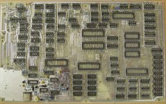
Jim, one interesting thing about the picture in the article on the Cortex II is that it also has the RGB video modification daughter board installed. I also found it interesting that they rotated the board 180 degrees to put the floppy and serial connections on the right side of the machine, instead of on the left.
 
Is that compared to the Cortex 1 ?
There are cutouts in the Cortex 2 case for the connectors.

I've not been through all the user group magazines yet.
Did they publish a pcb layput for the RGB board ?
I remember seeing the circuits but not a board layout.

Jim
 
Jim, what's the caption for the board top left of the photo, partially sitting over the PSU board? The caption is truncated in the scan - "...onics board"? Has a long ribbon cable leading off somewhere.
 
Jim, what's the caption for the board top left of the photo, partially sitting over the PSU board? The caption is truncated in the scan - "...onics board"? Has a long ribbon cable leading off somewhere.

Unfortunatly i don't have the originals for the PCN article, just the scans as you see them.
I bought a DVD of scanned PCN magazines off the net.
One of the user group magazines does have a poor quality reprint of the same article, i wonder if that has the fuil legend.
 
I wonder if that is the "E-Bus Electronics Board" to allow substitution of the 74LS2001. If you look where the cable goes, it leads back to the right area of the board. It is probably one of the 74LS2001 replacement boards as described about a year later in ETI in conjunction with the article on the serial board with the joystick input, as the layout looks about right for that one.
 
The new board is getting there.
It's somewhat better spec than the original would have been.
All new IC sockets, i didn't fancy 30 year old ones.
1% resistors , because thats what we have draws of here at work and the kit was missing resistors and caps.
Tant caps instead of electrolytics, mainly because electrolytic caps have progressed since Cortex days and now are a lot smaller pitch for the same values.
I could have formed the cap legs to the larger pitch but it never looks pretty and tants are a better spec and the correct pin spacings.
Just got a few more to find. The 5n6 Polystryrene cap is proving interesting to find.

Jim

Cortex MB nearly there.jpg
 
I just got TWO sets of bare Cortex boards to play with. Looks like this is going to be an interesting winter! :)
 
RGB interface.

RGB interface.

Found this on the net and backed it up to my site, an official Texas RGB (and composite) interface for the TMS9929 chips.
Looks a bit more comprehensive that the "Official" Cortex one.

http://www.quantums.info/cortex/SPPA004A_9928-29_9118-28_Interface_to_Monitors.pdf

Also copied the Texas TMS9929 datasheet.
http://www.quantums.info/cortex/TMS9918A 9928A 9929A.pdf

Has anybody got a copy of the later TMS9118 9128 9129 data sheets, i can only find part of one with just the electric specs on.

Jim
 
Has anybody got a copy of the later TMS9118 9128 9129 data sheets, i can only find part of one with just the electric specs on.

It's available cheap in hard-copy:

<http://www.abebooks.com/servlet/SearchResults?tn=TMS9118,+TMS9128,+TMS9129+data+manual>

(Remove the space in "manual" at the end of the link)

Stuart.
 
Jim, what's the caption for the board top left of the photo, partially sitting over the PSU board? The caption is truncated in the scan - "...onics board"? Has a long ribbon cable leading off somewhere.

To answer my own question, its the Centronics parallel printer port.

I've managed to get a full copy of the Cortex II manual - its a copy of the copy that sold on Ebay a few months ago. The chap who bought it does volunteer work for the UK's National Museum of Computing, and was happy to do a photocopy for me. Jim has at least some of the pages of the full manual, but I'm not sure if he has all of it. So I've scanned and published it here:

<www.avjd51.dsl.pipex.com/tm990/Powertran_Cortex_II_Manual.pdf>

Feel free to take a copy. Ksarul - could you possibly upload it to ftp.whtech for posterity?

Stuart.
 
Last edited:
Hi Stuart,
No, i didn't have the full manual, just what i'd uploaded so many thanks for that.
Some useful extra pages.
The page at the end about the 2 versions of the transistors supplied (with different pinouts) had me worried but luckily i seem to have the versions correct for the PCB silkscreen.

Jim
 
I'll put it up on WHT once I get my account there sorted out again--it doesn't like my FTP clients lately. . .
 
The full version of the Cortex 2 manual still seems to have C31 and C32 mixed up with different values on the parts list and schematics.
And disagreement between the schematic and the build instructions if to fit C31 in parallel with R77 (video Schematic), or across the pins of IC70(Page 32 sect 2).

Lots of fun working that one out, i'll let you know.

Jim
 
Does ayone have one of the MPE Parallel cards with the two joystick ports on it from the 1985 article? I'm looking for a picture of the bottom of it.
 
ETI tended to put the pcb layouts at the end of the magazine for people who made there own pcb's.
So it may not have been scanned in with the article.
Worth a look, i can look tonight.

Jim
 
E-Bus connector.

E-Bus connector.

Anybody know what connector is fitted for the E-Bus on the motherboard.
I thought it should be female (i.e no pins) but the pin labeling on the pcb (rows A and C) only matchs up with a male connector.

Theres no hole for it in the Cortex 2 case so was it connected to expansion boards with ribbon cable ?

Thanks,

Jim

Looking at the E-Bus motherboards on ...

<http://quarndon.co.uk/index.php?main_page=index&cPath=54_55>

... they have female connectors (as far as I can see), so the boards would be male, so the Cortex should also be female?

Have you got signal/pinouts for the E-Bus so you can check the signal connections against the pins? Give me a shout if not and I'll scan a copy.

Stuart.
 
Hi Stuart,
I had that thought as well and looked there.
But, i'm sure i read somewhere that the Cortex looks like another card not a motherboard so that would make it male like the cards.
The parallel port ETI article mentions the connector beinh male on the cortex but in electronics i quite often find that male and female get mixed up depending on what the person describing it decides is the male or female part of the connector.
The pins or the housing.
The pc legend for connector rows A and C and pins 1 and 32 matches up with a male connector i have but then the male connector numbering doesn't match up with a female connector when plugged into it !!!

Many thanks,
I have all the ETI articles and the 74LS2001 datasheet and patent.
I don't think i have an actual pinout of the E-bus other than whats in the Crotex data.

Many thanks,

Jim
 
Back
Top