- VCF South West - June 14 - 16, Davidson-Gundy Alumni Center at University of Texas at Dallas
- VCF West - Aug 2 - 3, Computer History Museum, Mountain View, CA
- VCF Midwest - Sept 7 - 8 2024, Schaumburg, IL
- VCF SoCal - Mid February 2025, Location TBD, Southern CA
- VCF East - April 2025, Infoage Museum, Wall NJ
-
Please review our updated Terms and Rules here
- Forums
- Companies
- IBM Computers, PCs, Clones and Descendants
- PCs and Clones (XT and early AT class machines)
You are using an out of date browser. It may not display this or other websites correctly.
You should upgrade or use an alternative browser.
You should upgrade or use an alternative browser.
IBM 5154 Troubleshooting
- Thread starter dongfeng
- Start date

bjorn_and
Experienced Member
Hi!
Just wanted to say thank you also: I got an IBM 5154 today (my second one) basically for free since it was not horizontally centered and about a half character width on the left side was distorted. The owner, who dug up this IBM 5160 with the EGA monitor from his storage was about to throw it away when he thought he might as well put up an ad for it. He knew nothing about computers and didn't even realize there was a problem with the monitor until I showed it to him. I got the 5160 and the monitor for less than $30 and hoped I could fix the monitor.
I found this thread, adjusted the horizontal phase as Dizzy33 did, and it's working perfectly again")
.
.
.
Too bad it caught fire just while I was writing this.. The picture was perfectly fine all the while it was smoking and sounding like a camp fire. I pulled the plug, ran with it to the bathroom, where I could handle a fire better (living in an apartment and the bathroom is all ceramic tiles so it felt safest, not because I was going to pour water on it.)
Opened it up but no traces of any burning! I couldn't find a single component that had burnt, examined the main board everywhere with a flashlight, no soot except on the inside of the casing. I tried to see inside the video and power unit but couldn't see anything suspicious, and the smoke looked like it was coming from the middle of the monitor. Weird, could it have been dust? It didn't smell like the typical smell of burnt electronics. I inserted the power plug again and no smoke.
Connected it to the computer, works perfect.
I tried to blow away some dust, but there was really not that much. It has been standing in a damp place probably, I can see signs of corrosion at some places, but not anything that scares me.
Another thing, there are four rubber wedges where the "neck" is connected to the picture tube (right between the copper wiring and the tube. They seem to be glued and held into place by plain tape. Two of those wedges have fallen off since the tape is all dried up and the glue has apparently lost it's grip. If I handle the monitor carefully (I guess it's some kind of bump protection?) do I need to care about these? They will be hard to re-attach without taking the whole monitor apart.
This fire is weird, any ideas what might have happened?
If I start using it again, I sure wont leave it unattended!
/Björn
Just wanted to say thank you also: I got an IBM 5154 today (my second one) basically for free since it was not horizontally centered and about a half character width on the left side was distorted. The owner, who dug up this IBM 5160 with the EGA monitor from his storage was about to throw it away when he thought he might as well put up an ad for it. He knew nothing about computers and didn't even realize there was a problem with the monitor until I showed it to him. I got the 5160 and the monitor for less than $30 and hoped I could fix the monitor.
I found this thread, adjusted the horizontal phase as Dizzy33 did, and it's working perfectly again
.
.
.
Too bad it caught fire just while I was writing this.. The picture was perfectly fine all the while it was smoking and sounding like a camp fire. I pulled the plug, ran with it to the bathroom, where I could handle a fire better (living in an apartment and the bathroom is all ceramic tiles so it felt safest, not because I was going to pour water on it.)
Opened it up but no traces of any burning! I couldn't find a single component that had burnt, examined the main board everywhere with a flashlight, no soot except on the inside of the casing. I tried to see inside the video and power unit but couldn't see anything suspicious, and the smoke looked like it was coming from the middle of the monitor. Weird, could it have been dust? It didn't smell like the typical smell of burnt electronics. I inserted the power plug again and no smoke.
Connected it to the computer, works perfect.
I tried to blow away some dust, but there was really not that much. It has been standing in a damp place probably, I can see signs of corrosion at some places, but not anything that scares me.
Another thing, there are four rubber wedges where the "neck" is connected to the picture tube (right between the copper wiring and the tube. They seem to be glued and held into place by plain tape. Two of those wedges have fallen off since the tape is all dried up and the glue has apparently lost it's grip. If I handle the monitor carefully (I guess it's some kind of bump protection?) do I need to care about these? They will be hard to re-attach without taking the whole monitor apart.
This fire is weird, any ideas what might have happened?
If I start using it again, I sure wont leave it unattended!
/Björn
modem7
10k Member
The "copper wiring" are the vertical and horizontal deflection coils. The rubber wedges are positioned during the convergence portion of the monitor's alignment procedure. An internet search shows that the following is typical text from an alignment procedure:Another thing, there are four rubber wedges where the "neck" is connected to the picture tube (right between the copper wiring and the tube. They seem to be glued and held into place by plain tape. Two of those wedges have fallen off since the tape is all dried up and the glue has apparently lost it's grip. If I handle the monitor carefully (I guess it's some kind of bump protection?)
"Remove the DY wedges and slightly tilt the deflection yoke horizontally and vertically to obtain the good overall convergence. Fix them after the good overall convergence is obtained."
I think so. If two have come off already, that suggests that the remaining two may follow relatively soon. It will be easier to fix the current situation than later when all four are off.do I need to care about these?
bjorn_and
Experienced Member
Thanks.
Now I feel a bit ashamed I tend to do these things very late at night when the rest of the family is at sleep and it was getting very late for me too. I realized those wedges must be there to align the coils when I woke up. However, the picture is aligned well and fixing this means I have to tear down the whole monitor which is simply not worth it since I have a second monitor in much better shape, assuming all that needs to be fixed is the vertical deflector chip. I might do this at some point, but not right now.
Also, I didn't read the whole thread, only the pages that Google directed me at which describes the adjustment of the horizontal alignment.
Now that I read the whole thread, I realize the smoke must have originated from the PSU since I couldn't see any trace of burning on the motherboard. That the smoke seemed to come from the middle of the monitor must have been just a coincidence or I didn't pay attention properly, it went quite fast between discovering it and trying to do something about it.
This maybe sound totally irresponsible, so please yell at me if I'm an idiot So, I don't intend to use the monitor for a long time without fixing it, but if it works, as it does now, there shouldn't be much risk in continuing using until I get the other monitor back and I can give this monitor some TLC?
/Björn
Now I feel a bit ashamed
I tend to do these things very late at night when the rest of the family is at sleep and it was getting very late for me too. I realized those wedges must be there to align the coils when I woke up. However, the picture is aligned well and fixing this means I have to tear down the whole monitor which is simply not worth it since I have a second monitor in much better shape, assuming all that needs to be fixed is the vertical deflector chip. I might do this at some point, but not right now.Also, I didn't read the whole thread, only the pages that Google directed me at which describes the adjustment of the horizontal alignment.
Now that I read the whole thread, I realize the smoke must have originated from the PSU since I couldn't see any trace of burning on the motherboard. That the smoke seemed to come from the middle of the monitor must have been just a coincidence or I didn't pay attention properly, it went quite fast between discovering it and trying to do something about it.
This maybe sound totally irresponsible, so please yell at me if I'm an idiot
So, I don't intend to use the monitor for a long time without fixing it, but if it works, as it does now, there shouldn't be much risk in continuing using until I get the other monitor back and I can give this monitor some TLC?/Björn
The "copper wiring" are the vertical and horizontal deflection coils. The rubber wedges are positioned during the convergence portion of the monitor's alignment procedure. An internet search shows that the following is typical text from an alignment procedure:
"Remove the DY wedges and slightly tilt the deflection yoke horizontally and vertically to obtain the good overall convergence. Fix them after the good overall convergence is obtained."
I think so. If two have come off already, that suggests that the remaining two may follow relatively soon. It will be easier to fix the current situation than later when all four are off.
Roland Huisman
Veteran Member
I'd restore a 5154 for some time ago. It's not only the mains filtercaps which are bad.
After replacing the mains caps it worked for another 10 minutes and the
next problem showed up. The next problem was the frame which collapsed.
Besides many bad solderings the most of all electrolytic caps were bad.
Some caps were the half of the original capicity and others had a strongly raised ESR.
I'd replace them all, resulting in a very good working monitor.
I have a lot experience restoring old vacuum tube and transistor based televisions.
The most not linear distortions in the picture are bad capacitors. Bad decoupling caps
can cause amplifier circuits clip or degrade amplifying and many other problems...
My original post on a Dutch forum:
http://www.philipsradios.nl/forum/index.php?mode=thread&id=6144
Auto translated:
http://translate.google.nl/translat...l/forum/index.php?mode=thread&id=6144&act=url
Regards, Roland
Last edited:
bjorn_and
Experienced Member
Yes, that is probably the most sensible thing to do. Once I get my other monitor working and enough spare time, I'll make this my winter project.
Thanks for showing me the thread, it will probably be useful!
/Björn
Thanks for showing me the thread, it will probably be useful!
/Björn
I'd restore a 5154 for some time ago. It's not only the mains filtercaps which are bad.
After replacing the mains caps it worked for another 10 minutes and the
next problem showed up. The next problem was the frame which collapsed.
Besides many bad solderings the most of all electrolytic caps were bad.
Some caps were the half of the original capicity and others had a strongly raised ESR.
I'd replace them all, resulting in a very good working monitor.
I have a lot experience restoring old vacuum tube and transistor based televisions.
The most not linear distortions in the picture are bad capacitors. Bad decoupling caps
can cause amplifier circuits clip or degrade amplifying and many other problems...
My original post on a Dutch forum:
http://www.philipsradios.nl/forum/index.php?mode=thread&id=6144
Auto translated:
http://translate.google.nl/translat...l/forum/index.php?mode=thread&id=6144&act=url
Regards, Roland
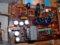
The fire/smoke was most likely caused by one of the mains suppression caps located on the
circuit board in the power supply cage. I've seen two of these smoke in the past. Because
its a suppression cap, the monitor will still function even though the cap is burned.
In the 1st attached picture of a 5154 power supply you can see one of these caps that burned
in the upper left section of the picture. Its marked .1uf X2. This one caused LOTS of smoke
when it burned.
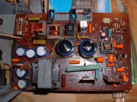
In the second attached picture the electrolytic capacitors are circled. I've repaired several
5154 power supplies by replacing all of these capacitors. You can probably get by with not
replacing the two large capacitors in the center of the board, they're usually okay and cost
about $4 apiece.
circuit board in the power supply cage. I've seen two of these smoke in the past. Because
its a suppression cap, the monitor will still function even though the cap is burned.
In the 1st attached picture of a 5154 power supply you can see one of these caps that burned
in the upper left section of the picture. Its marked .1uf X2. This one caused LOTS of smoke
when it burned.
In the second attached picture the electrolytic capacitors are circled. I've repaired several
5154 power supplies by replacing all of these capacitors. You can probably get by with not
replacing the two large capacitors in the center of the board, they're usually okay and cost
about $4 apiece.
Attachments
Last edited:
bjorn_and
Experienced Member
Thanks!
Yes, I believe so too. Great I get so many pictures and descriptions. Makes things so much easier later on when I'll do the work. I'll take everything apart as soon as I get the time, it may take a while, and see if I replace all caps or if I just do the ones visibly bad. It depends a lot on how hard it is to take everything apart again if I need to.
The picture is very good otherwise, bright, sharp and good geometry. I rather touch as little as possible.
/Björn
The fire/smoke was most likely caused by one of the mains suppression caps located on the
circuit board in the power supply cage. I've seen two of these smoke in the past. Because
its a suppression cap, the monitor will still function even though the cap is burned.
In the 1st attached picture of a 5154 power supply you can see one of these caps that burned
in the upper left section of the picture. Its marked .1uf X2. This one caused LOTS of smoke
when it burned.
In the second attached picture the electrolytic capacitors are circled. I've repaired several
5154 power supplies by replacing all of these capacitors. You can probably get by with not
replacing the two large capacitors in the center of the board, they're usually okay and cost
about $4 apiece.
GeneralMichaelXT
New Member
Hi There
I know i am abit late but i recently purchased an IBM 5154 from ebay and now that i try it, it made a very quite crackling noise and now it doesn't work. The only thing that seemed damaged was the fuse. But i was wondering would there be anything that caused the fuse to blow. Also, has someone got an image of an open IBM 5154 but the power supply intact. I am not quite sure on how to get the power supply back in properly.
I know i am abit late but i recently purchased an IBM 5154 from ebay and now that i try it, it made a very quite crackling noise and now it doesn't work. The only thing that seemed damaged was the fuse. But i was wondering would there be anything that caused the fuse to blow. Also, has someone got an image of an open IBM 5154 but the power supply intact. I am not quite sure on how to get the power supply back in properly.
modem7
10k Member
Lots. Any component failure that results in significantly more current being drawn from the power supply than normal. Or, the problem cause could be in the power supply itself.I know i am abit late but i recently purchased an IBM 5154 from ebay and now that i try it, it made a very quite crackling noise and now it doesn't work. The only thing that seemed damaged was the fuse. But i was wondering would there be anything that caused the fuse to blow.
You question tells me that you do not know much about electronics. If you haven't already, you should adequately educate yourself as to the hazards/risks of working in a CRT based monitor.
Have you done a thorough visual inspection?
I'm in Melbourne too. If you are prepared to drop off the monitor at my house, and collect later, then I will (freely) take a look at it. PM me if you are interested.
It has been a day since you posted. Did you work it out, or do you want me to post a photo of my opened 5154 ?Also, has someone got an image of an open IBM 5154 but the power supply intact. I am not quite sure on how to get the power supply back in properly.
Floppies_only
Veteran Member
It has been a day since you posted. Did you work it out, or do you want me to post a photo of my opened 5154 ?
I wonder if there is any interest in the Sam's Photofacts for the IBM 5154 EGA monitor. Perhaps people could PM me - I know exactly where the CD is at home.
Sean
Wavy 5154
Wavy 5154
I'll dig this thread up as others have done in the hope that someone who knows a lot more than I do about the 5154 can help me. I recently paid a rather princely sum for a "working" 5154 to replace my existing 5153. The seller did a bang up job of shipping it safely, but unfortunately it isn't the picture of health. It powers on without drama, but instead of the steady white raster, the whole display "wiggles" at ~60hz. Upon connecting it to the Cirrus GD510A in my 5160, the output image exhibits the same behavior.
I've tried alternating between color and enhanced modes on the card, as well as setting it to CGA, EGA, and auto. Same behavior regardless, and running CHECKIT's video test shows a wavy grid (see pic). I read through the thread and didn't see anyone with the exact same issue, so I'm not sure where to begin. I've re-capped plenty of other hardware, and opening it up doesn't scare me, but my proficiency level is that of targeted parts replacer, not diagnostic technician.
I could use some advise about the likelihood of being able to repair it easily, as I can still return it. If I open it up though, I own it. On the other hand, these don't show up every day, and it got here in one piece which is half the battle. It's also in very good cosmetic condition, neither mode 1 nor mode 2 have suffered vertical collapse, and the phosphor is crisp and bright. If the repair is relatively straightforward, my preference would be to keep it.
Any thoughts?
As a follow-up to yesterday's post, I notice that the intensity of the image instability (wiggle, waviness, or whatever) inherit to my new 5154 is cyclical and has a period of about 1min. When you first power the monitor on, the line-to-line horizontal offset makes the screen image appear wavy, but within 30sec or so, it's vibrating so quickly everything is just fuzzy. Give it another 30sec and we're back to the slow waves. Not sure if that helps...
After discussing the problem with the seller, he agreed to allow me to open it up for inspection before returning it. I guess I'd hoped to see something obvious, but don't see any overt problems (leaking electrolyte, burned components, etc.). I've attached a pic of the power supply after removing it from its housing. The tops of the big filter caps are a little puffy, but I think that's just the plastic covers. Otherwise the caps all look okay (that's glue not electrolyte under some of them I believe, as it's also present elsewhere). Since the small electrolytics C11, C13, & C14 were implicated on the first page of this thread, I pulled and tested each. They're fine too. Perhaps I'm barking up the wrong tree?

modem7
10k Member
From memory, those caps in my 5154 are the same; slightly rounded tops.The tops of the big filter caps are a little puffy, but I think that's just the plastic covers.
Yes, large electrolytic capacitors were often glued to the PCB. As shown in the photo at [here].(that's glue not electrolyte under some of them I believe, as it's also present elsewhere)
I know you are hoing to hear something like, "Keep it, because the problem will be easy to diagnose." You will not hear that from me, because I presume that you have no test equipment, such as an oscilloscope.I could use some advise about the likelihood of being able to repair it easily, as I can still return it.
Did your visual inspection include a thorough inspection of the solder joints?
Deteriorated electrolyic capacitors are common. Replacing all of those (starting with the power supply) may be the answer. But maybe not.
I'm not really too invested in either outcome. If I can't figure it out and a solution isn't forthcoming, I'll send it back. Conversely, this 12 page thread contains several success stories where someone presented a problem, a knowledgeable forum member suggested replacing the such and such (C11, TDA2653A, etc.), and a 5154 was saved from oblivion.
I do possess an oscilloscope, a few other half-decent pieces of diagnostic equipment, as well as the requisite solder re-work station. Since posting, I've been working through the diagnostics outlined in the SAMs 5154 publication (which I purchased from them for $22), but haven't solved it yet. You're right though, I'm no expert, and my first hope is that someone would see the photo and say "Hey! Mine was doing that! You need to replace / adjust <insert component>".
To this point, I'm most of the way through the PS, which now has several new caps and its outputs are to spec. I don't see any suspect solder joints there or elsewhere, and any that looked the least bit suspect have been reflowed. Thanks for the suggestions.
I have several 5154's but I've never seen that symptom....all the problems I've had with 5154's were related to bad
capacitors in the power supply.
It almost looks like the degaussing coil is 'stuck' or constantly on....although I would think the symptoms would be more severe.
The degaussing coil is connected to the power supply on the top far right gray connector of your picture. You could try
powering on with the coil disconnected. I think that black rectangular component with C02200 is the thermistor control
for the degaussing coil.
Edit: Looking at the diagram the degaussing coil might actually go to the center gray connector.
It may also help to check the AC ripple on the power supply output voltages. The diagram below shows the power supply layout.
Last edited:
modem7
10k Member
And I would expect it to affect both horizontal and vertical.It almost looks like the degaussing coil is 'stuck' or constantly on....although I would think the symptoms would be more severe.
Two steps forward, one step back...
I finished reflowing some suspect solder joints, re-capping and testing the PS output, and I then re-capped the video board for good measure (I cleaned out a couple of local Radio Shack stores that were closing last month, and now have years worth of 80% off electrolytics). After buttoning everything up, I turned it on and eureka! Stable images is both mode 1 and mode 2. I was about to take a picture of the screen in EGA Coloring Book to post whilst claiming victory when... *!POP!* and acrid smoke started pouring out of the PS. I'd just riveted that sum-b closed too
I'll wait for it to chill out overnight, discharge the CRT, and yank it back apart. The caps I installed were all new, of higher temperature rating (105C vs. 85C), and at or over the specified voltage ratings, so I'm not sure who didn't bring their A-game. Good news is that it was still happily displaying a stable image when I mashed the EPO button. More to follow...
modem7
10k Member
It is looking like none of the readers has seen that particular symptom on a 5154.and my first hope is that someone would see the photo and say "Hey! Mine was doing that! You need to replace / adjust <insert component>".
Although the description of "wavy edges" in post #2 sounds similar, I suspect that was something like pictured at [here], caused by poor voltage regulation in the power supply. Your symptom is different (you have horizontal lines shifting left/right rather than changing length).
Generally, such suggestions are based on known causes of certain symptoms.Conversely, this 12 page thread contains several success stories where someone presented a problem, a knowledgeable forum member suggested replacing the such and such (C11, TDA2653A, etc.), and a 5154 was saved from oblivion.
But sometimes, a symptom can have multiple possible causes, such as was revealed in the 5154 thread at [here].
If we summarise your symptom as 'horizontal ripple', the database at [here] shows multiple possible causes:
* Adds 2020 - horiontal ripple - faulty diode.
* Gateway PMV1448NI - horiontal ripple - faulty capacitors (small value)
* Kimsync F15LS - horizontal ripple - faulty FBT
* Philips 1557AS - mild horiontal ripple - faulty capacitor
* Wyse 50 - "Hori squiggly, ripple or static" - "If all caps check ok, replace flyback"
That will help a lot.I do possess an oscilloscope, a few other half-decent pieces of diagnostic equipment ...
So I presume that you are now going to move to the horizontal stage.To this point, I'm most of the way through the PS, which now has several new caps and its outputs are to spec.