• Please review our updated Terms and Rules here

IBM Model F Keyboard voltage issue

PCFreek

Experienced Member
Joined
Apr 5, 2013
Messages
322
Location
Florida USA
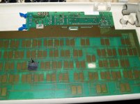
I have an IBM keyboard model F keyboard that does not work. I have tried swapping cords with a known good board and have verified that the cord is OK.

I have taken voltages on the boards of a known good and the non-working board. Voltages at the caps and resistors is all good... however, voltages at the large chip (shown as 8048 in the Technical Reference) are quite different between the known good and non-working board. The known good board has no voltage on pins 27 through 38. The non-working keyboard has +5v at all of these pins.

I cannot find a datasheet on the 8048, and my chip is not an 8048. I do not know if this voltage can be an internal chip problem, or if the keyboard is energized when it should not be. Any suggestions?

EDIT: datasheet link below.

P8140218.jpg
 
Last edited:
8048 datasheet here

Unless i am reading this wrong, page 8 of the datasheet says that these pins (port 2) are supposed to be +5v:

"The lines of ports 1 and 2 are called quasi-bidirectional because of a special output circuit structure which allows each line to serve as an input and output or both even though outputs are statically latched. Figure 7 shows the circuit configuration in detail. Each line is continuously pulled to VCC through a resistive device of relatively high impedance."
 
Last edited:
I thought more about this last night and assume that the ports can be pulled high or low. The datasheet is very long and I have not thoroughly digested it yet. I would assume that the good keyboard is pulled low (which must be correct since it works), and the bad keyboard is being pulled high. I will not be able to probe any further until Monday. If this isn't something that is controlled by a smaller chip on the board, then I would suspect the 8048 has a problem.
 
If you have ever wondered what the inside of the keyboard looks like... and this keyboard is still not repaired. any suggestions?

P1019517.jpgP1019513.jpgP1019515.jpgP1019516.jpg
 

Attachments

  • P1019514.jpg
    P1019514.jpg
    92.2 KB · Views: 3
Last edited:
I have taken voltages on the boards of a known good and the non-working board.
Are the two keyboards identical? If not, then to be kept in the back of the mind is that 'apples are not being compared with apples'.

... the large chip (shown as 8048 in the Technical Reference)
... and my chip is not an 8048.
This device will have IBM-authored code in its ROM.
The "8493518" on it is possibly an IBM part number.
Although not stamped "8048", the device is possibly a customised 8048 made for IBM by Intel.
 
The keyboards are the same (as shown in the photos below).
P8220220.jpgP8220222.jpg

I probed all of the IC's for voltage (not data) and found that many pins on chip U2 (14 pin chip in the middle) have 5v present at the pins where 5v is not present on the working board.
The following pins have no voltage on the good board, but have +5v on the non-working board: 4, 5, 6, and 8.

Looking at the keyboard schematics, I see that pin 8 is "data in" for the 8048. This leads me to believe that the problem may lie with the IC in U2. I cannot find a datasheet on it.
Keyboard schematics:
KEYBOARD.jpg
 
Last edited:
U2 is what is called a Tri-State Buffer with active low control. It appears to be a 4 input-output IC. Let me have a look to see if I can find something pin equivalent...

Edit: This one seems suitable http://www.ti.com/lit/ds/symlink/dm54125.pdf

This is a simple 74125 quad tri-state buffer IC. I quickly checked the pin assignments for the buffers (they all match). The only thing I have NOT checked is the pin assignment for the +5v and gnd. You can check this using a multimeter on your current IC - if it matches you could try replacing the IC with this equivalent one. I would say its 99% certain that it will.

Element14 sell them for about $1.30AUD - http://au.element14.com/texas-instruments/sn74abt125n/universal-bus-function-ic/dp/2371182
 
Last edited:
Just read your explanation again - Pin 5 on U2 should never have +5V on it. Pin 5 is tied to the ground rail. This does not point to an IC failure - rather a trace on the board / cable failure. I would check that A) this pin isn't dry soldered onto the board and B) that pin has continuity with ground with another point (check while unplugged) i.e. pin A05 on plug 1 and C) the ground is continuous between the cable & PC.

This should fix up your problem. If you ground is floating it will never work.

Pin 5 of U2 definitely has voltage. Pin 5 resistance to ground is 1.4K ohms between the pin and ground input pin with no cable attached. I also tested resistance between pin 5 and the keyboard shielding and got the same result. Resistance between keyboard shielding and the ground input pin is around 1ohm. the cable has been confirmed as good with a working keyboard. I'll check the solder joint on pin 5 and start checking other ground points for continuity. i appreciate your advice. I also saw this on the schematics, but I am not that good with reading schematics so i was unsure if this was a hard ground or a filter cap etc... I know what a cap looks like on the schematic, but am just never 100% sure.
 
I am back to thinking it is the 8048... I pulled out the logic probe and went over all 3 IC's.
The good board (verified as working) has pulses on the following pins:
U1 (8048 ) : 2-6, 7-14, 17-20, 22, and 30.
U3 (Chip on the far right): 4
No pulses are found at the keyboard connector unless keys are depressed.

The bad board has no pulses anywhere. Since pulses are not found at the connector, they must all be generated on the keyboard circuit board itself. Pin 4 of U3 does not have continuity with pins on the 8048 (R= around 1M), so it obviously does not feed the signal to the 8048. With all this, I deduce that the 8048 should be generating pulses and is not. Internal failure could also be sending 5v to the ground rail. I am not willing to remove a good 8048 from another board and try this. I did not find a keyboard ROM online. since the 8048 requires a ROM (and I don't even have the knowledge or equipment to burn a chip), this keyboard may be DOA. Bought it on eBay as "worked perfectly when stored, untested at time of sale and sold as-is". I am beginning to think that "untested" means "does not work".
 
How are you determining which pin is 1,2,3,4 etc on the IC's? The only reason I ask is that based on your last set of results your working keyboard should not work. A lot of those pins you found pulses on are tied to the ground or +5V rails. Where did you find your circuit diagram? It's possible it is the wrong diagram (although unlikely as the keyboard controller chip Vcc,Vdd and Gnd are always in the same place).

Could you have a look at that datasheet I posted up earlier of U2 and make sure your system of pin numbering is correct? I don't mean to be rude or anything by the way; I just don't quite see how your working keyboard works with the results you posted :)

Can you also do the following checks on both the working and non-working keyboard? This will narrow things down even further.

Check the resistance from the ground input pin (connector P1 A05) to:
- Pins 20,6,7 of U1
- Pins 2,13,5,7,10 of U2
- Pins A01,A03,A07,A09 of connector P2

Check the resistance from the +5 input pin (Connector P1 A01) to:
- Pins 26,40 of U1
- Pin 14 of U2
- Pin A08 of connector P2

You can then also plug everything back in and then check the voltages at those pins. All of the ground pins should have 0V at all times and all the +5 pins should have +5 at all times.
 
Last edited:
How are you determining which pin is 1,2,3,4 etc on the IC's? The only reason I ask is that based on your last set of results your working keyboard should not work. A lot of those pins you found pulses on are tied to the ground or +5V rails. Where did you find your circuit diagram? It's possible it is the wrong diagram (although unlikely as the keyboard controller chip Vcc,Vdd and Gnd are always in the same place).

I follow/count the pins as shown in the sketch below. The diagram that I provided is from the IBM 5150 Technical Reference Manual. I will check all readings again. It is a very fair question to wonder if I am making an error on counting the pins. It would not be the first time I made a mistake. :)

I appreciate your help.
IC pins.jpg
 
Could you have a look at that datasheet I posted up earlier of U2 and make sure your system of pin numbering is correct? I don't mean to be rude or anything by the way; I just don't quite see how your working keyboard works with the results you posted :)

My pin numbering is correct... perhaps my IC numbers are incorrect? I know the 8048 is U1, but I assumed the other 2 IC's were U2 and U3 in order. See photo below. My voltages for the non-working board are written on the sheet of paper.

I'll do the checks that you requested now.P1019549.jpg
 
Can you also do the following checks on both the working and non-working keyboard? This will narrow things down even further.

Check the resistance from the ground input pin (connector P1 A05) to:
- Pins 20,6,7 of U1
- Pins 2,13,5,7,10 of U2
- Pins A01,A03,A07,A09 of connector P2

Check the resistance from the +5 input pin (Connector P1 A01) to:
- Pins 26,40 of U1
- Pin 14 of U2
- Pin A08 of connector P2
Good board:
Check the resistance from the ground input pin (connector P1 A05) to:
- Pins 20 .3ohm ,6 2k ohm,7 1k ohm of U1
- Pins 2 open,13 open,5 3k ohm,7 1k ohm,10 3k ohm of U2
- Pins A01,A03,A07,A09 of connector P2 there is no connector P2... that's the traces to the keys.

Check the resistance from the +5 input pin (Connector P1 A01) to:
- Pins 26 0.1 ohm,40 0.1 ohm of U1
- Pin 14 0.1 ohm of U2
- Pin A08 of connector P2

Bad board:
Check the resistance from the ground input pin (connector P1 A05) to:
- Pins 20 0.1ohm ,6 2k ohm,7 0.1 ohm of U1
- Pins 2 34M ohm,13 open,5 3k ohm,7 0.1 ohm,10 3k ohm of U2
- Pins A01,A03,A07,A09 of connector P2 there is no connector P2... that's the traces to the keys.

Check the resistance from the +5 input pin (Connector P1 A01) to:
- Pins 26 0.3 ohm,40 0.3 ohm of U1
- Pin 14 0.1 ohm of U2
- Pin A08 of connector P2

The only difference in the 2 resistance readings is that pin 7 of both U1 and U2 is grounded on the bad board. I'll check voltages next.
 
You can then also plug everything back in and then check the voltages at those pins. All of the ground pins should have 0V at all times and all the +5 pins should have +5 at all times.

GOOD BOARD:

Voltages on ground pins:
- Pins 20,6,7 of U1 All 0v
- Pins 2,13,5,7,10 of U2 All 0v except: 10=5v and 13=1.7v

Voltages on the +5 input pins:
- Pins 26,40 of U1 All=+5v
- Pin 14 of U2 =+5v
- Pin A08 of connector P2

BAD BOARD:
Voltages on ground pins:
- Pins 20,6,7 of U1 All 0v except pin 6=5v
- Pins 2,13,5,7,10 of U2 All 0v except: 5= 5v, 10=5v, and 13=1.7v

Voltages on the +5 input pins:
- Pins 26,40 of U1 All=+5v
- Pin 14 of U2 =+5v
- Pin A08 of connector P2

So all the readings are the same except for +5v on U1 pin 6 and U2 pin 5 of the bad board.
 
... perhaps my IC numbers are incorrect? I know the 8048 is U1, but I assumed the other 2 IC's were U2 and U3 in order.
They are in that order according to SAMS Computerfacts, although I see that both the SAMS and the IBM Technical Reference use 'M' rather than 'U' as a chip prefix.

5160_kyb_from_sams_computerfacts.jpg
 
I thought that you would have at least seen a single 20 ms pulse coming in on the clock line from the 5150/5160.
Refer to the diagram [here].

No pulses coming in from the computer on either the good or bad board. a test of the cable (verified as working with the good board) reveals no pulses when not plugged in to P1 on the keyboard. I detect pulses on both data lines on the good board when a key is pressed, but never on the bad board.
 
Last edited:
I thought that you would have at least seen a single 20 ms pulse coming in on the clock line from the 5150/5160.
Refer to the diagram [here].

I see what you are saying... a pulse during POST... yes, I verify 3 distinct single pulses:
1 almost immediately upon power switch being flipped
2nd pulse is about 2 seconds later
3rd pulse is right before the floppy is accessed during POST (several seconds after power on). this is the pulse you are referring to.
 
Hold on - is this an 83 key XT keyboard or the 101 key AT style?

The 83 key XT model has a different diagram (attached below courtesy of modem7's site)
83-Key Keyboard.jpg

That came out a little small... Have a look here at page 117 of the PDF (section 4-21) http://www.minuszerodegrees.net/manuals/IBM_5155_5160_Technical_Reference_6280089_MAR86.pdf

This makes a lot more sense out of the readings you were getting. I'll see if I can come up with some more ideas from this.
 
Back
Top