• Please review our updated Terms and Rules here

HP 7510A, possible vector monitor ?

Thank you for the link! I have taken a look at service manual and found which was the problem with my camera! The connector was backwards!. Now it works!. By the way, i have found it takes a lot of time to complete a picture. For instance, demo 3 takes about 2 minutes to expose at 400 ASA. May this long time be normal?.

Which Contax adapter have you ordered? Mine is Fotodiox, the cheap version (15usd).

If you fiddle with the links I sent you, you should be able to get the user guide and that says that long exposure times are normal.

The one I ordered was also about 15 US so of a similar ilk. It does say will focus to infinity so hopefully it just works...
 
The one I ordered was also about 15 US so of a similar ilk. It does say will focus to infinity so hopefully it just works...[/QUOTE]

The problem is you cannot adjust focus, as the lens in the camera module is fixed. So, as you put an adapter in between the camera and the lens there is an immediate out of focus effect that you cannot fix because there is no focus ring. To fix this problem you would need to change the position of the camera/lens set with regards to the mirror. As the distance is so short, a slight change will have a huge focus effect. The focus is so critical that, in the service manual, there is a caution about not replacing the plastic enclosure with another one because the set lens/enclosure is custom made to fit one each other.
 
I must read the service manual! That implies even if we swapped cameras it might be out of focus.

I do have a "Plan B" . I have ordered a lens reversing ring that's intended for putting the main lens on the wrong way round for Macro Use. I figured I could use it to build an adjustable mount, perhaps 3-D printed. It would be nice if I could get another camera box to mess with, but I think that's highly unlikely...
 
Dave, which is the target camera for which you have ordered the Contax adapter?
fortunately Contax has a pretty large FFD of 45.5mm, so any camera with less than this length might work (e.g.Canon).
My adapter is for a 47mm camera, which would explain the out of focus issue i am seeing.
Another factor to consider is that many digital cameras have a big bulging grip on the right hand side, which might prevent the camera to be attached to the lens. The Contax camera is perfectly flat on the front side, so it does not have this problem.
 
I ordered if for a Fuji X-Mount fory XE-1 which also has a very flat front... thats the new digital, not the old FujiFilm X mount which is different. Apparently that has an FFD of 17.7 mm which I think explains why the adaptors look very deep,

http://photo.stackexchange.com/ques...rt-flange-back-distance-improve-image-quality

but of course as the sensor size is only 23.6 mm x 15.6 mm compared to 36 × 24 for the contrax so I assume am only going to see the middle 2/3 of the frame, which is why I ordered some other bits to see if I could mount the camera differently. I wonder if the plugs used on the camra box to interface to the main body are still available. It looks really delicate, but it would be nice to make a box. Would also be usefull to have a plug for the Camra lean then

AS the Camera works I guess I could try some film in it......

http://www.amazon.co.uk/Fuji-Superia-X-TRA-400-36-Colour/dp/B0009NDJLK/
 
Much to my surprise...

1. The adaptor arrived today and it fits the supplied box.
2. My Fuji XE-1 Camera fits the other end.
3. This display is reasonably "in focus"
4. It records the images on "B" if I manually hold the shutter in....
5. The exposure looks about right , but I think the colors are out...

BUT BUT BUT BUT

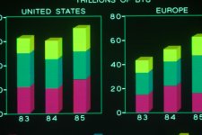
the image is cropped, as I expected. First sample uploaded

DSCF0438.jpg

oddly I had to set the file orientation to "Horizontal" to get minimum cropping. Now I just need to figure out how to tap into the shutter release....
 
Very nice!. to me it looks slightly out of focus, although it can be the image compression effect?.
The schematics of the connector is described on the service manual,page 210. Look for Connector P3 on the camera module. Pin-2 is labeled "trigger". This should be enough to recreate an electronic shutter for the camera, provided it has an electronic trigger of course. i own a XPRO1 but sadly it does not have an electronic release. Does the XE have one?.
 
Not sure if that's positioning of the Camera or the digital processing, or the focus of the screen. I want to experiment with the digital processing options in the Camera but at 2 minutes per exposure and then another two minutes (or more) for the camera to save the collected image its going to take some time and I just popped into the "computer room" whilst I was in the middle of cooking a meal, to try the fitting, so "watch this space"..

oh and i can't stop it down as there is no Iris, as there is no lens on the Camera, it just uses the one in the box....

The XE1 has an electronic release that's accessible by both the microphone socket and the USB socket so that should be simple enough. Plenty of circuits on the net, and I bought an el-cheapo one from e-bay to dismantle and see how it works and I will check out the connector..

Also plenty of ideas for solenoid operated remotes for cameras without a socket....

http://hackaday.com/2013/03/03/building-a-remote-control-for-a-cable-release-camera/
 
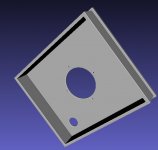
I have found the camera box has a cap in front which is single part (see picture below).
This cap is where the camera mount is attached with 4 screws. Glue is applied in the inside edges, probably after trying to find the right position, that is, the right distance to the internal lens. The lens itself is mounted on a second plastic part, and can be moved inside and out by rotating two threaded washers.
So, to make a new camera mount it should be enough to remove this cap and 3D-print a new one.
The bad side is the original cap seems to be glued to last forever, so probably it is not easy to remove without breaking the whole plastic thing.

7510a_cap.jpg
 
Yes I did see if it would spring off. It wouldn't !!!!

I took a few more pictures, Image Processing is turned off after the first one. I think they are slightly sharper...

DSCF0001.jpgDSCF0004.jpgDSCF0005.jpgDSCF0006.jpg
 
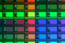
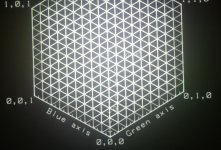
Looking at the palette sample, colors look right.
I can see noise however, but digital cameras are noisy at long exposures. For instance, how much time takes to generate the palette samples image ?

To prevent the cropping effect, you need the Sony RX1 full frame camera :-D
 
I think all the frames take between one and two minutes when the plotter is set for Fuji 400 ASA film. I also set the Camera to 400ASA.

I did look at the RX1 but had to lie down in a dark place when I saw the price.... :(

... The next thing is to try plotting from a computer. Sadly my favourite HPGL program plays Hangman and that's not going to work on this, but I am sure I have one or two that work...
I did hack the SIMH IBM1130 emulator to plot HPGL. You can see it running a sample CSMP (so analogue computer simulation) here...

https://www.youtube.com/watch?v=SCUUgLvVvpg
 
It happens an interesting effect when sending hpgl data to the 7510A.
The 7510A has only 16KB of data buffer. Half of this space is used to contain actual vector data and the remaining have vector attributes, like intensity (i believe intensity is not an attribute in hglp languagae, is it?). Each coordinate may take upto 14bits, and is relative to the former vector or absolute. That would mean you can store at most about 1000 vectors before the new vectors start to be stored on top of the former ones. The CRT 'stores' for some time the oldest vectors but then they fade away. You can save a lot of space using relative coordinates. What i do not understand is how the system is able to separate the colors in different exposure stages without loosing information. I dont know either if the system would lost data in the process. As you are able to actually record the full color output on your camera, please perform a test by sending a complex PLT image through serial port. Does it show fully on your camera?. I can provide some plt files if you want.
 
My plan is to:-

1. Generate .PLT files with Axis marks so I can check what the plotable area is.
2. Try running some of my sample HPLG ploting programs re-scaled so that they only use the area captured by my Camera. (so probably NOT the IBM 1130, and not the HangMan program)

but I would be happy to run some Plot Files from you through the beast. I have sent you a PM with my E-Mail address.
 
I have sent already a ZIP file containing 6 PLT files to your gmail address.
I challenge you to plot to your camera the file "HP6.PLT" !!
 
Hi there,
Is anyone still active on this thread? I just discovered it and it's very gratifying to see folks enthusiastically playing with 7510A's after all these years. It happens that I originated the project at HP in 1984, inspired by Colin Cantwell's use of some of our vector instrumentation displays to generate the wall monitor images for the movie "War Games". I've always done photography as a hobby, so I thought it would be interesting to take the digital-to-analog portion of that hardware, combine it with one of our high-resolution electrostatically-deflected medical imaging displays, put an HPGL plotter digital front end on it, and see if we could make a low-cost film recorder that was plug-in compatible with the HP pen plotters that were popular in the business graphics market at the time. I worked on all aspects of the product, especially the software and camera designs. The internal development project name was "Myopia", in recognition of my bad eyes and the fact that staring through microscopes at screens and slides was likely to make them worse. The entire project development was about a half-dozen folks, a software engineer to take the code from an HP pen plotter and make it drive a CRT and camera instead, a mechanical engineer, electrical engineers for the digital boards and one for the analog boards, a CRT guy who mixed custom phosphors for us, and a production engineer to figure out how to actually get it built.
The cameras were designed to be assembled once and never adjusted after that, so the lens was mounted in the front board to get the magnification right, and then the back was glued on at the right distance to be in focus. That operation actually used an early autofocus-advise camera from Canon (AL-1 QF) to tell the person building the camera when it was in focus. I was pretty proud of that little bit of cleverness.
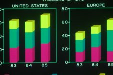
I developed all the test patterns and color tests you're seeing, and also did all the exposure calibrations for the various films we supported.
I'd love to hear more about what folks are doing with their machines. I have a pre-production prototype up in the attic - haven't turned it on in decades, but it might still work.
 
Hi inakito,
As the originator of the 7510A project and one of the software developers on it, I think I can answer your question.
The 7510A processed HPGL as it came in on the interface just like a plotter did, only instead of driving motors, we took the vector endpoint and color (pen selection and optional pen color settings) and built display lists for the CRT driver board in the three colors (RGB). When the buffers filled up, we ran the CRT through the three colors, moving the filter wheel as needed. Then we flushed the buffers and started filling them again. Since the film was adding up everything we did, there was no problem if the entire image didn't fit in memory at one time. I did some experiments with full-frame raster images (run-length encoded as thousands of horizontal line segments) that took hours to download and expose, but they worked. We did have some issues with thermal hysteresis in the analog amplifiers that could cause the spacing of "scan lines" to not be perfectly even, so there could be little black gaps in places. We tried various workarounds like ordering data to drive the amplifiers in symmetrically opposite directions to try to keep them evenly heated, but never really solved that one. So it goes.
Anyway, I really am thrilled to see folks still interested in the device. Hope you're having fun with it.
 
Back
Top