DrCharles
Experienced Member
Crickets over at cctalk, so thought I would post here on a DEC-specific forum 
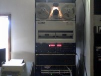
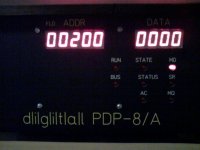
The 8/A's power supply, RL02's and RX01 is all working fine (knocking on wood)... so far, no return of the dreaded Power OK "flicker". Maybe it really is fixed this time.. Famous last words, I know!
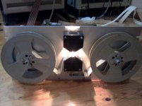
Now I am pondering my PC8E (M840) reader/punch control board, and a Slo-Syn TRP125 reel-to-reel photoelectric 8-bit paper tape reader that's been sitting unused in my other rack, probably for at least ten years when I got it very cheap. I'm thinking of interfacing them since I don't have a PC04 and no pressing need (or money) for one, although I do have the cables. The reader is already a TTL-level-compatible interface so that's one less thing to worry about. Anyway, the TRP125 can do 125 characters per second, not as good as the 300 of the PC04 but still much faster than the ASR-33 if I feel like messing with paper tapes...
The TRP125 just needs a single pulse of 30 us to 5 ms on either its forward pulse or reverse pulse inputs to move the tape one character, and the data is valid for a guaranteed 150 us after the pulse before the tape physically moves. Data can be read/strobed into the PC8E register any time the tape is not actually moving. (A real PC04 has a stepper motor controlled by the PC8E, so one of those four step outputs will probably work as a move pulse). Doubt I'd ever need to back up the tape one character.
Timing will need to be adjusted for the rep rate which is slower, since 1 character takes 8 ms on this one but 3.33 ms on the PC04. Also probably for some pulse widths. The clock is generated by a triggered multivibrator running at 1.67 ms, looks simple to tack on two additional capacitors to slow it down. I want to make as few mods as possible to the PC8E and they have to be easily reversible.
One thing missing from the TRP125 is a tape-out indication and motor stop, though. The TRP125 reel drive motors keep spinning until the tension arms are manually raised to a detent position that actuates microswitches to turn the motors off. The ASR-33 stops automatically when the tape has run out, which would be useful. I suppose I could add a microswitch to sense the presence of tape, or perhaps an LED/photocell to read the sprocket holes and provide pulses as the PC04 does. More of a mechanical challenge than an electrical one. Otherwise I'd have to "fake" the feed hole pulses (although it does look like I can just tie the Feed Hole line high and manually shut the reader off once the tape runs out).
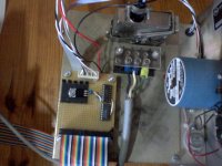
I added a power switch to the reader's front panel, which cuts off the AC and asserts the Reader Offline signal. Also a Tape Feed switch to that input on the PC8E. The cable is just a 40-pin ribbon with 22 grounds and the rest are signals. I made a little board with a 40-pin header and pigtails from there to the reader connector, and left room for any logic circuits if I need to add them.
I got lucky on ebay and found the exact Amphenol 26 mating connector that I needed, including the locking hood. Right now I'm waiting for it to come in the mail, so decided to check out the reader to see if everything worked. Today I found that channels 1-3 work, 4-7 didn't work but 8 did. I thought I had some bad transistors (at least one had been replaced sometime in the past). Changed one to start with, and that channel still would not work although the photodiodes were not dead. I took a closer look at the manual, although the only one available online is the later model TRP125A which has eight individual photodiode bias pots (mine has a board with 8 slightly-different precision resistors that must have been factory-selected). Anyhow it turned out that the lamp needed the focus and alignment adjusted. Its filament isn't perfectly aligned with the bulb axis. It's somewhat more critical than I thought. Then all bits toggled with tape running except bit 7. I spotted some mungus that had gotten on the photodiode lens and a cotton swab with 91% alcohol took care of that problem. Now all 8 bits do their thing. Ready for connection!
My Tek 114 pulse generator is useful for generating the tape move pulses. When cranked up to 8 ms (full 125 cps speed) that tape really moves. I've never seen a PC04 running at 300 but it must look impressive.


![P10-06-15_13.56[1].jpg P10-06-15_13.56[1].jpg](https://forum.vcfed.org/data/attachments/20/20613-1332f030e0acd1df8006a8a6c0b38942.jpg)


![P10-08-15_19.36[1].jpg P10-08-15_19.36[1].jpg](https://forum.vcfed.org/data/attachments/20/20635-117caef29d04503c4dce0ccc78ecd537.jpg)
