• Please review our updated Terms and Rules here

Identifying IBM PC XT model and year

With the resulting load the power supply started, ran the fan and produced +5.02V, -5.00V, +12.00V and -11.75V according to my DVM.
So, good result for a crude PSU test.

... there was no fan movement on the PS ...
Either the PSU did not start, or it started and then shutdown due to overload.

Results were > 8 MegOhms on -5V, +12V and -12V. The +5V test indicated 167.5 Ohms between pins 1 and 6 of P9 header. This is a confusing result because MZD diagnostic lists 200 Ohms as possibly good, and I don't see any obviously blown caps.
I am glad you used the word 'possibly', because at this point, there is no indication of a definite or even probable short circuit (full or partial) on the +5V line of the motherboard.

The Minimum Diagnostic Configuration (MDC) check being run cannot cater for all scenarios, just the majority.

It is a bit like the crude test that you have done of your PSU. Not a full functional test, and so what you have is only a certain level of confidence in it.

Is there any other diagnostic I could perform before replacing the 13 tantalum capacitors on the +5V rail?
Of course, assuming that the cause is on the +5V line, there would be a bunch of other components on the +5V line to be replaced after that.

Inadequate PSU loading is a possibility. The motherboard alone should (repeat: should) be enough of a load, but maybe deterioration (or other) in your PSU means that it needs more loading.
For example, that test 1.5 ohm resistor of your draws about 3.5 amps from the PSU's +5 volt line. The 5160 motherboard draws about 1.5 amps from the same line. Maybe your particular PSU (for whatever reason) needs 2 amps or more from that line in order to start. Who knows! It is certainly a path worth investigating before replacing a lot of capacitors.
IDE drives in addition to the motherboard?


The 5160 motherboard does not require +12V/-12V/-5V. In the 5160, those are for possible use of expansion cards. Do you have another source of +5V that you could use to power the motherboard, one that can supply up to 10 watts? If so, note that:
1. The +5V line would not only need to go to the appropriate pin on P9, but it also needs to go to the motherboard's POWER GOOD line (the pin that the orange wire on P8 goes to).
2. 10 watts is not much. Certainly enough for the motherboard, expecting to hear the beeps that the MDC produces.


An ATX power supply via adapter (e.g. eBay item 351628918812) ?
 
Are we having fun yet?

Are we having fun yet?

Either the PSU did not start, or it started and then shutdown due to overload.
Thanks for your reply.

Before I performed the 1.5 Ohm load test on the power supply (while the PS was out of the case and not attached to the motherboard) I tried powering it up unloaded. I noticed that the fan moved for a fraction of a second before stopping. Once there was a load on the supply it continued to move and produce the voltages I noted earlier.

When I reinstalled the PS in the case, after I connected to the motherboard and began the MDC testing, the fan did not move at all, even briefly. Before I start replacing capacitors I will try adding an additional load to the supply. The simplest thing for me to do is to add back in the cards and drives; i.e. fully populate the system, and see if it will light up.

An ATX power supply via adapter (e.g. eBay item 351628918812) ?
I do have other ATX supplies. I could use one of those if I had an adapter; I found the StarTech 20-to-12-pin adapter several places on line: typically $9 for the adapter and $15 for the shipping. Aaargh. MicroCenter is right down the street from me and they don't carry it. I also have a couple of RadioShack switching power supplies that can supply 5 Volts - in theory; never used them.

I take it the Power Good signal is required for the board to initialize?

-CH-
 
I take it the Power Good signal is required for the board to initialize?
The Power Good signal is initially low (TTL low). The 5160's PSU takes it high (TTL high) when all PSU output voltages have reached specification and are stable.
The motherboard ('knowing' that the voltage rails are 'good') then takes itself out of the reset state (see [here]).

In doing what I suggested earlier, the motherboard's Power Good line is going to go high earlier than normal.

Note that on some 5160 motherboards, the motherboard may start without its Power Good line being connected to anything at all. In those cases, it will be because pin 11 on the 8284A chip is 'floating' high. (Diagram [here])

Thank you for your reply. It's way beyond my knowledge but let's recap:

Power is off, voltage rails in PC are at or near 0 VDC, clock chip pin 11 (should be) tied to power good P8 pin1.
Power supply switch allows 120 VAC into the supply.
Supply starts to build DC voltages +-5V, +-12V.
PS monitors load on supply and holds P8 pin 1 low until (voltage? amperage?) reaches acceptable level and holds that level for X amount of time.
If supply target is reached P8 pin 1 outputs +5VDC and clock chip pin 11 (RST, TTL low) goes high and the system comes out of reset.
If supply does not reach acceptable level the monitor inhibits the supply.

If the above is accurate, may I ask:

Obviously the fan runs on 12VDC generated by the PS; otherwise it would turn all the time 120VAC was switched on. Presumably it stops because the power supply monitors conditions and shuts down the PS. But there are two indicators; two states for the fan: One where the fan turns briefly, then stops; the other where the fan never turns at all. It's understandable that the fan would turn briefly until the monitor circuit decides to shut down. What condition keeps the fan from turning at all? A short on one of the rails, e.g. bad cap, would produce an over-amperage / under-voltage situation, and presumably the monitor circuit would detect that and shut down the PS. But if that were the case shouldn't there be the brief pulse turning the fan while the monitor circuit waits to see whether targets are achieved? What is the signal / condition that inhibits the power supply to immediately shut down, and why would adding a greater load alleviate that condition?

I guess I'm confused because I ran the power supply with no load and observed the fan turn for a fraction of a second, I ran the power supply with a load and observed the fan start and run, and then I ran the power supply attached to the motherboard, with verified resistances on all four rails, and the fan never turned at all. If it's not a shorted capacitor at fault, what else could explain this behavior?

By the way, it is above and beyond the call of duty for you to answer these questions. I thank you for your willingness to put up with my inexperience.

-CH-
 
... with verified resistances on all four rails,
Again, confidence factor only. That is why in the MDC, you do not see the wording of, "If you measure XXX or above, there are no power issues on the YYY line."

Why not? Things change when voltage is applied:

For example, some of us have experienced passive components that only fail/misbehave when voltage is applied.

For example. You know from an earlier post of mine that the 5160 motherboard draws a nominal 1.5 amps from the +5 line. Ohm's law suggests that the resistance that you should measure on the motherboard's +5V line will be in the order of 3.5 ohms (5V/1.5A). Yet, on a good 5160 motherboard, what is measured ranges from hundreds to thousands of ohms. Why? Because of 'active' components.

What is the signal / condition that inhibits the power supply to immediately shut down
It comes down to the design of the power supply. Sometimes things do not behave as expected, and that behaviour is only explained if one delves deep enough. I could experiment with my 5160 power supply and come up with the various conditions under which that symptom appears, and then discover that the results are invalid for you because your 5160 power supply is different to mine (e.g. R12 is 10 ohms instead of 5 ohms, e.g. completely different board, ...)

By the way, it is above and beyond the call of duty for you to answer these questions. I thank you for your willingness to put up with my inexperience.
Yes, there is a point at which people will say, "You just have to trust me. I'm a doctor."

At this point, both your power supply and motherboard are still under suspicion. A known good power supply should prove things one way or the other.

And while you are waiting for a known good power supply, you can try the additional loading (motherboard plus xxxxx).
 
At this point, both your power supply and motherboard are still under suspicion. A known good power supply should prove things one way or the other.

And while you are waiting for a known good power supply, you can try the additional loading (motherboard plus xxxxx).

Took a little time off to take care of a personal matter. In the meantime I got a StarTech "ATX to AT Motherboard Power Converter Cable" for $8, free shipping, from Amazon. http://www.amazon.com/gp/product/B000E7JUVO

This comes with two extra lines which I believe are intended for connecting to a power switch. Not sure whether I need to bridge these in order for my PS to start but I will experiment.

But before I do any of that I will fully populate the system and give my OEM equipment a chance to spring into life. Chances of that happening are about as great as me trusting a doctor.

-CH-
 
This comes with two extra lines which I believe are intended for connecting to a power switch. Not sure whether I need to bridge these in order for my PS to start but I will experiment.
Yes, they are for a switch. Bridge with wire. There are no safety concerns (e.g. it is not 115Vac)
 
To my surprise the completely-assembled CPU system fired up the power supply and after some delay - more like 60 seconds than 5 - the A: drive light briefly flashed and the drive turned.
There were no beeps, which concerned me briefly, but the modem card speaker outlet connects to the PC speaker cable and also to the motherboard, so there may be a misconfiguration there. I will hook the system speaker to the mobo directly to see if I can get a beep.

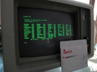
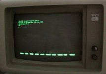
Encouraged by these results I added the monitor and keyboard to the CPU and powered up again. The monitor displayed a memory-OK count that went to around 640k and then the A: drive lit up again, this time in earnest. After not finding a disk the machine booted in Basic from ROM. Tested the keyboard to verify that commands were being accepted and acted upon; they were.

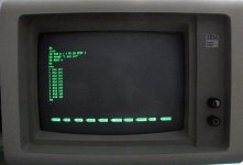
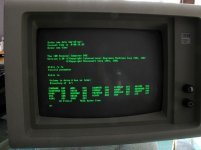
Pictures attached.

I want to thank everybody who offered their advice, particularly Modem7. I wonder if he/she is old enough to remember the archaic CP/M batch-file-transfer protocol and the days of dial-up bulletin-boards? I am.
In any case I apologize for my lack of knowledge; I am grateful for the assistance, without which I would never have gotten this far.

More to come; next to try a boot from disk and then to run an app; but thanks again.

-CH-

Q.jpgR.jpg
 
Disconnected modem's speaker output from system speaker and connected that to the motherboard directly; now we have a single beep after memory check, QED.

Received several IBM disks with the machine - a package deal from "the original owner" - but could not find a DOS disk that would boot.
One disk started the boot sequence and halted with a "missing sector" error. At least, I believe it was booting because I could hear the head advance through several tracks.
The other disks I tried from among that group simply (and quickly) turned once and booted from ROM.

I went to WinWorld and downloaded an image file of IBM DOS v.3.3 /5.25 disk. These are .img files, and Dunfield's ImageDisk tool wants to find an .imd file instead. But ImageDisk runs on DOS and my DOS machine has a 5.25 inch drive so I used the HxCFE software to convert formats. Very handy utility and thanks to SomeGuy for suggesting it.

My DOS machine, a '586, has a TEAC FD-55 GFR (DSHD, 1.2 Mb) drive and so I selected what I think are the appropriate settings and wrote the IBM image to a DSDD disk which I first erased with a strong magnet.
The write was successful, so far as I can tell, in that I am now able to boot the '586 machine with the IBM DOS disk that I burned there. However, the IBM PC XT does not want to boot from that disk and goes right to Basic ROM.

It may be possible - even likely - that one or both of the 5.25 drives is enough out of spec to make a disk written on one unreadable on the other. This raises some questions, however: What would you recommend doing?

I can replace my XT's A: drive with another Tandon TM-100 2A (like for like) which may also be out of alignment. If it doesn't boot either then I still don't know where the fault lies.
I can pull the XT's A: drive and try to use it to write the IBM DOS image while attached to my '586 machine, then move it back to the XT and see if it will boot from a disk that it wrote. If the XT TM can't communicate with the '586 controller what should I then conclude? And if the XT TM can write a file and read a file while attached to the "586, is the XT's FDC the likely culprit? Or the cable? or the B: drive?

Not sure where to go with this one, but the wife would like the XT off her dining room table before dinner.

-CH-
 
The only way to resolve any issue of this type is by substituting *known good* components, both hardware and software, one item at a time. Anything short of that method can surely lead to lunacy.

Whenever you use more than one item that is not known to be completely reliable you are introducing a degree of uncertainty that can not be readily resolved. IOW, every individually questionable component needs to be tested in a machine that is 100% reliable. Anything less than that is going to result in more 'spinning your wheels' and that just doesn't lead anywhere worthwhile.
 
My DOS machine, a '586, has a TEAC FD-55 GFR (DSHD, 1.2 Mb) drive and so I selected what I think are the appropriate settings and wrote the IBM image to a DSDD disk which I first erased with a strong magnet.
The write was successful, so far as I can tell, in that I am now able to boot the '586 machine with the IBM DOS disk that I burned there. However, the IBM PC XT does not want to boot from that disk and goes right to Basic ROM.

It may be possible - even likely - that one or both of the 5.25 drives is enough out of spec to make a disk written on one unreadable on the other. This raises some questions, however: What would you recommend doing?

I can replace my XT's A: drive with another Tandon TM-100 2A (like for like) which may also be out of alignment. If it doesn't boot either then I still don't know where the fault lies.
I can pull the XT's A: drive and try to use it to write the IBM DOS image while attached to my '586 machine, then move it back to the XT and see if it will boot from a disk that it wrote. If the XT TM can't communicate with the '586 controller what should I then conclude? And if the XT TM can write a file and read a file while attached to the "586, is the XT's FDC the likely culprit? Or the cable? or the B: drive?
I would not trust a 1.2mb drive to write a 360k disk at all. Chances are your "strong magnet" didn't get every last bit, and a single one left behind can trip things up. It is also easy to mess up double stepping and bit rates.

Ideally you should obtain a good quality half height 360k for your 586 or some similar system.

But short term your best bet is just to connect the tandon to your 586. Just be mindful of termination issues. That will let you directly format and verify the 360k disk to make sure it is readable. I sort of doubt it is an alignment issue. If you have a known good factory made 360k disk you can try reading it attached to the 586, and if that works OK then that rules out alignment. Even if it is alignment, then you should have a disk that will boot.

I'd also test out the other drive the same way while you are at it.

BTW, there is also a guide to converting standard sized IBM "IMG" files to Imagedisk format here: https://winworldpc.com/winboards/viewtopic.php?t=6931.
 
Thank you for your replies.

I do have other drives, both 360k and 1.2 Mb in 5.25 format, from TEAC, Panasonic, Fujitsu, Chinon, Tandon etc... The problem is that I can't be sure whether any are "known good quality" in the sense of meeting industry spec. I don't mean to rant but I could if I got off on the topic of purchasing used equipment - particularly used drives - through eBay. Suffice to say that the seller of the PC XT we are discussing here represented his sale as "...in excellent working order. "

A drive that is out of spec but "workable", i.e. can write, read its own writing and read an industry-produced disk, is not necessarily going to produce disks that another machine can read, as I have already found. I recently went through hundreds of factory-produced disks in order to retrieve their software so I could transfer it to DVD for more lasting storage. There were some disks that could be read by any drive, a number that only could be read with one drive and a handful that could not be read with that drive but could be read with another. Some of the factory disks were DSDD but many were DSHD, hence the FGR. I can fit a 360 to the 586. A known good one, who knows?

I tried to find an avenue for repair or refurbishment of 5.25-inch drives; most inquiries were met with silence. TEAC responded that they hadn't performed any floppy drive repairs for at least eight years and would not even quote a price. The Kryoflux people were perhaps a little hopeful when they told me, pre-sales, that there were "lots" of people on their forum who repaired floppies. The fact is that floppy repair is mostly a lost art and its difficult to charge enough to make it worthwhile. I believe that opinion has been echoed by others on this site.

So I decided I would learn to repair my own. I acquired a dual-channel scope and an alignment disk and have been scouring the Internet for service manuals and testing procedures. I bought books and I've learned how to do basic maintenance and testing, but radial and azimuth alignment are uncharted waters - as yet. I expect to get about half of the drives working well enough to be able to exchange disks with them and the rest will save for spare parts. You can guess that I have been kicking myself recently for giving away so many well-preserved, working specimens over the years.

The objective is to restore these old machines to working order, with period-correct peripherals and software. Its a learning opportunity for me but the learning curve is steep. Still, every little success is worth the effort, at least in my opinion. I'm crawling, but someday I may walk.

Having said all that, I think the best strategy is to attach the Tandon A: drive to the 586 and see if I can get it to communicate. If it does I will create another DOS disk on it and move everything back to the PC. I know that the last drive in the chain has to have a termination resistor (DIP) and I know where that goes. The B: drive is already suspect. I use Jim Drew's SuperCard Pro to do basic testing on these drives and already experienced an anomaly with that drive. I have other TM-100 2As I can substitute; I just used this one to create the load that Modem7 recommended.

Sorry for the diatribe. Thanks for your suggestions.

-CH-
 
I use v4.5 Norton Disk Test (DT.EXE) or Disk Doctor (NDD.EXE) to test floppies. I have found either of them to be highly efficient in checking floppy disks. Conversely, if you put a *known good* disk in a drive and run the test it will verify the veracity of that drive! No need to fuss with overly-complicated methods or tools when a simple one does the job just as well. KISS :)

Personally, I wouldn't make the Tandon drive my first choice for the 586 but rather my last as Tandons seem to be the least reliable. Use something else if you can. There's nothing quite like a good old, reliable 360K TEAC, IMHO.
 
I just used this one to create the load that Modem7 recommended.
The points go to Stone for his, "Sometimes PSUs can give misleading results when not fully loaded." at post #20. I simply secondonded that.

I tried to find an avenue for repair or refurbishment of 5.25-inch drives; most inquiries were met with silence. TEAC responded that they hadn't performed any floppy drive repairs for at least eight years and would not even quote a price. The Kryoflux people were perhaps a little hopeful when they told me, pre-sales, that there were "lots" of people on their forum who repaired floppies. The fact is that floppy repair is mostly a lost art and its difficult to charge enough to make it worthwhile. I believe that opinion has been echoed by others on this site.
I limit floppy drive repairs for other people to radial head alignment, replacement of short-circuit capacitors, connector reseating, and visually identifiable issues.

A few years ago, there was a US based forum member advertising that they repair 5.25" drives. I cannot remember the details.

... but radial and azimuth alignment are uncharted waters - as yet.
All of the 5.25" floppy drive manuals that I have read, indicate that if the azimuth alignment is out of spec, replacement of the head assembly is the repair procedure.

As for azimuth alignment on the TM100s, when you loosen the securing screws that are indicated, only loosen lightly. If too loose, the just-achieved alignment will be lost when the screws are re-tightened.

Its a learning opportunity for me but the learning curve is steep. Still, every little success is worth the effort, at least in my opinion. I'm crawling, but someday I may walk.
Exactly. And the more difficult the success, the more rewarding it is.

particularly Modem7. I wonder if he/she is old enough to remember the archaic CP/M batch-file-transfer protocol and the days of dial-up bulletin-boards?
Yes, hence my handle. Quite a few of us have 'been around for a while'.
 
I use v4.5 Norton Disk Test (DT.EXE) or Disk Doctor (NDD.EXE) to test floppies. I have found either of them to be highly efficient in checking floppy disks. Conversely, if you put a *known good* disk in a drive and run the test it will verify the veracity of that drive! No need to fuss with overly-complicated methods or tools when a simple one does the job just as well. KISS :)

Thank you for your replies.

Personally, I wouldn't make the Tandon drive my first choice for the 586 but rather my last as Tandons seem to be the least reliable. Use something else if you can. There's nothing quite like a good old, reliable 360K TEAC, IMHO.

Thanks for the tip. For some reason I never used the Norton Utilities, but I found them on WinWorld and will give them a whirl (spin?). Tandon will only go on the 586 long enough to verify its abilities. I had a TEAC 1.2 GFR on the 586 for my floppy archive project but can replace it with a TEAC 360. Thought I would give it the alignment procedure first, tho.

Thanks again for the suggestions. OSFTSB.

-CH-
 
Once again... I would make an alignment procedure the *last* thing to do -- anytime.

I have thousands upon thousands of floppies and dozens of floppy drives that I have been using for ~ 25 years. In all that time I have never done an alignment on any drive. The problems have always been with the disks, themselves. If you attempt an alignment on a drive that doesn't need it the best outcome would be 'no change' and the worst would be to make any further use of that drive impossible. IOW, alignment should always be the last resort, if any at all.
 
Once again, my thanks for your replies.

Progress update: Took the PC XT A: drive (the one with the termination resistor array) out and attached it to the 586. Using the ImageDisk program and this drive I burned a new disk containing IBM DOS 3.3. While still attached to the 586 I tested the disk with the DIR command, got a directory, and stuck it back into the PC XT. The PC XT did not boot from the disk I had just made on the same drive. "Disk boot error".

I took the suspect drive back to the 586, reattached it and tried to boot from it there. Same result, same error.

I substituted one of the other TM-100 2As lying around and once again burned a copy of DOS 3.3 on this new drive. After the CTL-ALT-DEL three-finger salute the machine booted into IBM DOS 3.3.

Took my new A: drive back to the XT and installed it. This time the PC booted into DOS 3.3. Tested a few commands; results OK. Tried to address the B: drive on the XT; got an error reading the disk the A: drive had produced.

Got a commercially-produced disk and tested that. Once again the A: drive would read and execute the commercially-recorded information, but the B: drive would not.

From this I concluded that the "new" A: drive was in spec and the B: drive was not. I went back to my pile of Tandons and attached another to the 586. Using the same disk as had been prepared by my "new" A: drive - now on the XT - the 586 booted into IBM DOS 3.3. Of course the terminal resistor, in place while the drive is a single, will have to come off when this becomes the "new" B: drive on the XT.

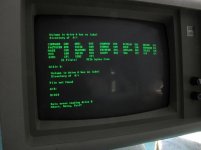
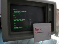
For those of you scoring at home: 5 Tandons, 2 of them work. Pictures attached.

Thanks again,

-CH-

S.jpg T.jpg U.jpg V.jpg
 
For those of you scoring at home: 5 Tandons, 2 of them work. Pictures attached.
Why am I not surprised? :)

You should still verify whatever floppy disk(s) you are using for this process with Norton DT.EXE to ascertain that none of the failures you have noted are in any way disk related. And, you should do this on the most reliable floppy drive in your arsenal.
 
And, you should do this on the most reliable floppy drive in your arsenal.

I'm still figuring that out. But I have a baseline, at least: I have two 5.2.5 TM drives that agree with one another and both can read commercial titles. I also have a couple of disks that one of the two drives wrote that I can use to test other drives for compatibility. All of the other drives are half-height, except for the ones in the Kaypros, and that's another story.

I now have a machine that boots from a floppy and can read and write standard disks from either drive. My thanks to the VC community for all their help in achieving that milestone.

I have inspected the disks that came with the machine; most are readable except for the modem diagnostic disk. I suspect that the jacket is binding; I know how to handle that. If I can read that disk I will see about testing the (1200 baud) modem. Reminds me of my first modem, a 300 baud that I used to dial up Compuserve. With a wife and two daughters in the house and only one phone line, I was not always the most popular guy.

I ran a BASICA mortgage program; calculations were so slow you could almost hear the processor counting. I got an Intel 8087 that I will add and see if I can note a difference. Also have an NEC v20. I know, heresy.

And I just love that high-persistence-phosphor green screen. Takes me back to the days of ANSI codes and character-based graphics. I think I still have some...

Lots left to do; I'll keep you posted. Thanks again for everyone's help.

-CH-

What? No pictures?
 
I have installed the 8087 co-processor without incident. Running a modified version of an IBM BASICA program that calculates mortgage amortization, I see a difference in speed, and perhaps in memory check at start up as well.

I have run the diagnostic tests on the IBM 1200 baud internal modem, hard-wired as COM1, and it passed all tests. No attempt yet to connect to another computer but I have a way to do so.

The ProPrinter received a new ribbon and has been tested for communication with the PC: slow, noisy and grainy character output, just as I remember. Lots of pin-feed paper, though.

The Tandon TM-100 2A (B: drive, fortunately) is acting flaky: sometimes throws an error, sometimes not. Sometimes on a read, sometimes on a write. Sometimes after long use, sometimes right away. Not sure about this one but eventually a hard drive will occupy that slot.

I have the NEC V20 chip but have not installed it as yet, partly because I want to ask about the AST SixPack Plus. I read the thread from several years ago with comments by Modem7 about his experiences. The compatibility issue might be a consideration, though apparently solvable, but the real questions are about the abilities of the AST SixPack Plus itself:

Can the RTC (clock) handle dates after Y2K? And can the AST board be used as expanded (i.e. up to 1 Mb) memory? I already have a functioning board that takes system memory from 256 to 640K.
If the AST clock is useless and the memory can't be used in conjuntion with my existing board then it won't be worth the trouble it might cause with the NEC processor. Or should I upgrade the BIOS anyway?

Thanks for your replies. Sorry if anyone is offended by my reference to an old thread.

-CH-
 
Back
Top