xjr358
Member
- Joined
- Dec 30, 2023
- Messages
- 23
Hello everyone,
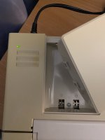
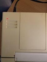
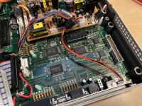
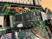
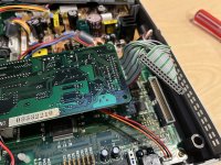
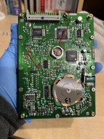
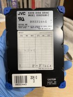
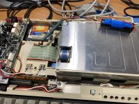
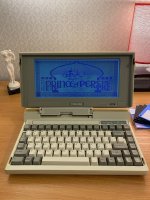
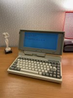
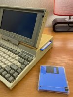
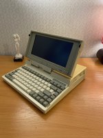
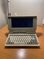
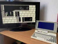
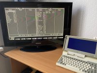
This time I want to share my experience with a T1200 repair/restoration project. I bought the laptop from eBay, it was a bit dusty and came with an original Toshiba power adapter. Thanks to this forum I knew this thing should be recapped there are leaking caps at the PSU and display backlit inverter. So I replaced them and it turned on and booted up from the floppy drive. As the built-in 20Mb MFM hard drive has not shown signs of life I decided to use 3inONEder Compact Flash adapter made by @Conventional Memories - and this is a complete game changer for Toshiba (and some other) laptops of that era. I installed the adapter and after some trials and errors managed to install DOS 5.0 at 1Gb compact flash card. It works like magic and allows you to do a lot of experiments with different OS and software. Huge thanks to @Conventional Memories for this product!
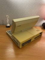
After some cleaning machine turned out lovely, there were a couple of issues that need to be addressed:
This time I want to share my experience with a T1200 repair/restoration project. I bought the laptop from eBay, it was a bit dusty and came with an original Toshiba power adapter. Thanks to this forum I knew this thing should be recapped there are leaking caps at the PSU and display backlit inverter. So I replaced them and it turned on and booted up from the floppy drive. As the built-in 20Mb MFM hard drive has not shown signs of life I decided to use 3inONEder Compact Flash adapter made by @Conventional Memories - and this is a complete game changer for Toshiba (and some other) laptops of that era. I installed the adapter and after some trials and errors managed to install DOS 5.0 at 1Gb compact flash card. It works like magic and allows you to do a lot of experiments with different OS and software. Huge thanks to @Conventional Memories for this product!
After some cleaning machine turned out lovely, there were a couple of issues that need to be addressed:
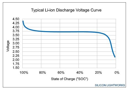
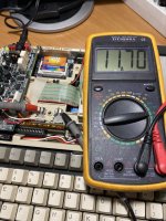
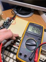
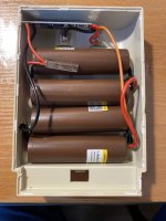
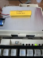
- Main battery to Lithium 18650 conversion
- CMOS battery replacement to CR2032
Attachments
-
 IMG_0106.jpeg2.8 MB · Views: 25
 -
 IMG_0105.jpeg2.9 MB · Views: 17
 -
 IMG_0103.jpeg2.5 MB · Views: 16
 -
 IMG_0101.jpeg2.5 MB · Views: 13
 -
 IMG_0100.jpeg2.7 MB · Views: 14
 -
 IMG_0093.jpeg2.9 MB · Views: 10
 -
 photo_2024-02-17 15.32.17.jpeg300.8 KB · Views: 11
 -
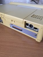 photo_2024-02-17 15.32.05.jpeg217.7 KB · Views: 19
 -
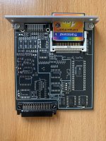 photo_2024-02-17 15.32.02.jpeg377.8 KB · Views: 29
") happy to see another one of my expansion cards put to good use.
happy to see another one of my expansion cards put to good use.