• Please review our updated Terms and Rules here

new PDP QBUS panel project

Title pretty much says it all. I put a new project on github
https://www.github.com/joelang/pdp-panel

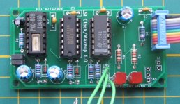
it's a panel for QBUS backplane with power supply control, bus power signals,LTC clock, run/halt with indicator.

joe

Joe,
I took a look at your design and like it a lot. I have a quad wide 4 slot Qbus back plane that I've been
wanting to hook up to a PC power supply. Your circuit boards and design look too make a very polished
design for a setup like that. In your github I did not see a bill of materials and also I was not familiar
with the microcontroller you used in the design.

Is there any chance that you have an extra set of boards that I could buy from you? I'd also be
interested in the controller chip, especially pre-programmed. If you are willing to sell me the boards
send me a private message and if not I'll see if I can get some boards made from your KiCad files.

It look like a very useful set up!

Thanks,
Mark
 
Using a microcontroller is cheating :)

View attachment 64587
View attachment 64588

[Note: This uses an RD-50A power supply (<20 USD) rather than a PC power supply, but was otherwise built with parts on hand]

https://hackaday.io/project/156536-building-a-pdp-11


It's not cheating when the micro costs a buck and uses less PCB area. ;^)
if you've figured out all the micro is doing is LTC. It's just an oscillator / divider, it will feel like more of a cheat.
I'm also using it with miniITX supply i got for less than $20. My panel was also "parts on hand" except the switches.

joe

Actually... Just to add to the pissing match. When I designed my pdp11 switch panel I used these, MM5369AA

Less board space than both. Still available on ebay.

Enjoy.
 
As I had an original, working PX0-600 clock generator, I made a classic 74LS14 capacitor based delay for BPOK and BDCOK. More an old-style solution ;-). Mostly working, all but the SRUN_L LED.
 

Attachments

  • clock-wakeup_1.0small.jpg
    clock-wakeup_1.0small.jpg
    67.1 KB · Views: 7
Last edited:
As I had an original, working PX0-600 clock generator, I made a classic 74LS14 capacitor based delay for BPOK and BDCOK. More an old-style solution ;-). Mostly working, all but the SRUN_L LED.

Nice looking board.
I did The SRUN with a r/c network. weak pull up (led off) strong pull down from SRUN. 2 resistors 1 cap and a diode.

joe
 
As I had an original, working PX0-600 clock generator, I made a classic 74LS14 capacitor based delay for BPOK and BDCOK. More an old-style solution ;-). Mostly working, all but the SRUN_L LED.
[power-down sequencing] Much the same way as the original DEC circuit I copied it from, with a diode...

Hi -- I'd be very interested if you could show us either your circuit diagram or the original DEC one. Many thanks!

Jonathan.
 
Some info (text, no diagram) can be found in this document, page 1-5:
EK-MIC11-TM-002_MicroPDP11_Systems_Technical_Manual_Sep85.pdf. The schematic referred above was derived (IIRC) from a PDP-11/03 schematic which I redrew in KiCAD with added the PX0-600 part. I use an ATX-power supply, so the clock had to be generated otherwise. But I thought the 11/03 was too complicated for me, and ended up with the LSI_CLOCK_WAKEUP schematic. The EK-LSI-TM-002.pdf document seems to contain most information (starting around page 11-8).

The clock signal (BEVNT) appears to be present only at the top-most slot of my H9275-A backplane. Could not find info which confirmed this.

Fred Jan
 

Attachments

  • PDP11_03_Light_and_Switch_Borad.sch.pdf
    80.3 KB · Views: 10
I know it's a sysgen option, but 50/60Hz selectable makes it good for the rest of us!

Thanks for sharing...
 
I don't expect to be able to pull a color burst crystal far enough off frequency to get an integer divide for 50 hz.
Several of the common baud rate crystals would work If you change the timer divisor. Can't do it with just a jumper.

joe
 
For reference, here is the DEC schematic for the PDP 11/03-L Front Panel
PDP11-03L Front Panel.png
A few things to note:
- S1 is the RESTART switch. It is debounced by R19/C7 and the LM339 comparator.
- S2 is the HALT/RUN switch. It is not debounced.
- S3 is the LTC disable switch (as shown, with W2 installed). It is not debounced.
- The RUN light can be driven by the RUN/HALT switch (W3 in, W4 out) or by the SRUN L signal from the processor (W3 out, W4 in).
The SRUN L signal is not a constant value, so is extended by the 74123 retriggerable one-shot. This is not strictly necessary -
the LED will still light if driven directly from the SRUN L signal, but at diminished brightness due to the flicker.
- BPOK H is always asserted and does not appear to follow the Power Up/Power Down sequence shown here:
sequence.jpg
 
I don't expect to be able to pull a color burst crystal far enough off frequency to get an integer divide for 50 hz.
Several of the common baud rate crystals would work If you change the timer divisor. Can't do it with just a jumper.

joe
If my math is correct, you can get to within 1.4ppm of 50Hz assuming a perfect 3.579545MHz crystal.
Assume an actual crystal with a frequency tolerance of 10ppm and stability of 30ppm.
What's the problem?

But (to Radix:)) why would 50Hz even be needed unless there is software that specifically requires it? DEC operating systems are configurable for 50 or 60Hz. The line frequency just happens to be an easy thing to extract...
 
Before I decided to use the PX0-600, I was thinking about using a 2457600 Hz crystal and a 74HC4060, divide by 8192 to 300 Hz. Then a selectable division by 5 or 6 (could be a 7490) to get 60 or 50 Hz. Would have been an option for the second version of the LTC board which never happened.

Fred Jan
 
If my math is correct, you can get to within 1.4ppm of 50Hz assuming a perfect 3.579545MHz crystal.
Assume an actual crystal with a frequency tolerance of 10ppm and stability of 30ppm.
What's the problem?

But (to Radix:)) why would 50Hz even be needed unless there is software that specifically requires it? DEC operating systems are configurable for 50 or 60Hz. The line frequency just happens to be an easy thing to extract...
You cant get there with a 16 bit counter. You would need to prescale the clock to the timer. The lowest clock divisor is 8.
3579545 divided by 8= 447443.125 not a good starting place to get to either 50 or 60 hz.
You could use a lower divisor and do additional division in the interrupt service routine or change the divisor each timer overflow to get a non integer divide.
But it starts to feel like a hack.

If you choose a common baud rate crystal like 3.6864 mhz. as the starting point the numbers work for both 50 or 60hz.
If i had intended to support both 50 and 60 hz this is ware I would start.

I never thought about supporting 50hz. as you questioned "Is it actually necessary".
 
Before I decided to use the PX0-600, I was thinking about using a 2457600 Hz crystal and a 74HC4060, divide by 8192 to 300 Hz. Then a selectable division by 5 or 6 (could be a 7490) to get 60 or 50 Hz. Would have been an option for the second version of the LTC board which never happened.

Fred Jan
Thats a better starting place to get 50 and 60 hz.
 
Back
Top