• Please review our updated Terms and Rules here

Osborne 1 boot

Tuukka

New Member
Joined
Aug 12, 2023
Messages
9
Hi,

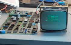
just got a dead Osborne 1 with a double density board. After the first tests, looks like the power supply is OK. Powering up the main board, the onboard beeper keeps beeping, and CRT monitor filament does not light.

Does the boot rom check for keyboard or disks at power up? I did not have those connected. Boot rom is just burned 1.44. Maybe next I will check the CPU signals (CPU chip itself verified good) but would like to know if keyboard or floppies are needed for boot. - Could the monitor keep its filament off because main board does not output correct sync pulses?

Tuukka
 
CPU has good clock, but something is keeping /RESET low. Going to check the reset circuitry next.
 
Some progress. The CPU held at reset was due to a bad CPU in a bad socket (the machine has spent last 30 years dismantled in a cardboard box, in a not very controlled environment). A new CPU and socket fixed that. Still no boot, but of course the boot ROM socket was just as bad. After replacing, the beeper went off at reset, and looking at the monitor signals with a scope showed nice H and V sync, with some activity in video also. But the monitor was still blank. Took out the monitor board and removed horizontal output transistor. Checked OK. Reinstalled with new silicone grease. Checked most electrolytics with an ESR tester. No major problems. Then re-soldered all coils and major possibly vibrating parts. Power on... and success!

So now I have the CPU board booting, but no floppy disks or keyboard attached yet. Next task will be to remove old grease and re-lubricate the floppies. My keyboard interconnect cable was removed. Is this the correct way to install it - and does the computer side connector then mount cable exiting left or right?
 

Attachments

  • 20230814_141832.jpg
    20230814_141832.jpg
    111.3 KB · Views: 7
  • 20230814_171351.jpg
    20230814_171351.jpg
    519.7 KB · Views: 6
Last edited:
Found some pictures to clarify the keyboard cable installation. Floppy drives were dead, so had to replace the disk controller socket also, but now the machine and both drives works fine, except some return scan lines are visible on CRT. I did not found a G2 adjustment at the monitor, so that will have to do for now.

Compared to a Kaypro, this machine is a pain to disassemble & put back together!
 
Finally, it does work!

I already put it all together, but couldn't stand the CRT retrace lines and light screen background.
Now this usually needs adjustment of the CRT G2 voltage, but it is not available on the Zenith monitor on my Osborne.

Locating the G2 input to CRT fortunately was easy, since the CRT connections were labelled on board. Connecting a 2.7 megohm resistor from G2 (orange wire to CRT) to ground reduced G2 voltage so that the front panel brightness control is now able to turn raster completely off.

And of course, this needed one more round in disassembling/assembling the whole stuff. I guess I am getting to learn to do that :)
 
Hi @Tuukka ,

Welcome to the board. Looks like you solved all your problems before anyone could respond.

I'm curious that you weren't able to get rid of the retrace with the pots alone?

David
 
The brightness control did not "go low enough", and the usual G2 adjustment trimpot is not present on this monitor. Some resistor in the HV circuitry might be aging and changed value, but since I didn't find a schematic for the monitor, and the G2 wire was clearly labelled, I took the easy way. The picture looks very good, no burns on CRT and very sharp focus after adjustment (there is a focus pot). I guess this machine has not been used very much.
 
Did have some stability problems on the machine at cold boot - replacing all electrolytic capacitors on the power supply resulted in rock solid machine. They were 40 years old after all!
 
I might have another one coming, but for now it is unreachable because of snow :) Also a Kaypro II.
 
Back
Top