• Please review our updated Terms and Rules here

486 Troubleshooting assistance... data lines all high etc

Chr$

Experienced Member
Joined
Aug 13, 2021
Messages
155
Location
Saxony, Germany
Hello.

I have a Gigabyte GA486-US motherboard, which looks exactly like this:


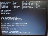
Cosmetically it's very nice, there has been no battery leakage, so that's always a good start. With CPU, 4 sticks of RAM and post card plugged in I just get dashes shown and no beeps.

I have of course checked the jumpers to the best of my ability and dumped the AMI BIOS, which also looks normal and has a date of 12/12/1991.

CPU has 5v and 33.33mhz clock signal.
Reset starts high and goes low as normal.

I have a basic oscilloscope and noob-class knowledge on these matters. I've prodded the address and data lines on the ISA bus and get the following:

All data lines are stuck high (4.88v, which is the same as what the PSU puts out as 5v as measured on the power connector).
A18, A17 and A29 are all stuck at 0v.
All of the other address lines are stuck at 3.6v.

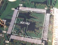
Next to the ISA slots there are a number of 74(x)245 and 74(x)244 as well as a 74F373. I have identified 5 chips that have connections to the data and address pins on the ISA slots.

Is it a good idea to change those 5? Should I concentrate on the buffer chips with connections to the lines that are stuck low first? I'd love to hear how others would go about further troubleshooting and am grateful for any tips.

(I've attached the BIOS dump to this post as I am not a member on Retroweb and in case anyone would like to add it to the 486US resource)
 

Attachments

  • 486 GA486US AMIBIOS 27C512.zip
    41.6 KB · Views: 3
I have a basic oscilloscope and noob-class knowledge on these matters. I've prodded the address and data lines on the ISA bus and get the following:

All data lines are stuck high (4.88v, which is the same as what the PSU puts out as 5v as measured on the power connector).
A18, A17 and A29 are all stuck at 0v.
All of the other address lines are stuck at 3.6v.
So by 'stuck', from the time that the power switch is turned on, the quoted lines never change state.

(I've attached the BIOS dump to this post as I am not a member on Retroweb and in case anyone would like to add it to the 486US resource)
Retroweb may want to see your motherboard running first, i.e. BIOS known to be undamaged.

I'd love to hear how others would go about further troubleshooting and am grateful for any tips.
Have you re-seated all socketed chips?

Tried a known-good CPU ?

I see that your motherboard has a {RTC chip + battery, in a plastic case} module on it. Something that is always a concern.
 
So by 'stuck', from the time that the power switch is turned on, the quoted lines never change state.


Retroweb may want to see your motherboard running first, i.e. BIOS known to be undamaged.


Have you re-seated all socketed chips?

Tried a known-good CPU ?

I see that your motherboard has a {RTC chip + battery, in a plastic case} module on it. Something that is always a concern.
1. Correct, the levels go up and stay there. No activity. Actually, looking at my notes, A19 goes to 4v, not 3.6v. And the 3 that are stuck at 0v obviously don't move at all.
2. Yes, makes sense to add it if/when I get this working.
3. Yes. Only the BIOS ROM and the cache chips are socketed and I have a device for testing various RAM chips so also tested each of the cache chips and they all came out good.
4. There is no RTC in plastic case (e.g. Dallas module or similar). It had a barrel Ni-Cd originally and has a 4 pin header for an external battery. I also tried to boot it with an external battery plugged in and it made no difference.

Oh, and yes, I'm testing with a known working 486 33mhz SX chip.
 
Today I checked to see if I could find any activity anywhere, e.g. on either side of the LS245 buffer chips, around the chipset chips, on the BIOS ROM etc and apart from the crystal oscillators oscillating there is no activity whatsoever, everything is stuck at 3.6 - 4v, 5v or 0v! I'll probably pull off some of the buffer chips around the ISA slots and test/replace them and if that gets me nowhere then I'll assume the chipset is dud, unless anyone has a better idea.
 
Fixed it!

That was a very rewarding repair. I remembered there had been some minor corrosion signs around some of the pins of one of the main chipset chips and as the whole thing is completely dead, i.e. no activity at all, I wondered if perhaps whatever caused that minor corrosion had got under the chip. So I removed the UM82C482AF and sure enough, there were some darkened areas. I buzzed the pin pads to their nearest via and one of them had no continuity. I traced it on the other side and it lead through another couple of vias to the CPU, more specifically its ADS# pin, which apparently needs to be asserted for the bus to work at all (I don't really know exactly what that means, but it sounded very important!). I fixed it with a very thin wire and also did some preventative maintenance on some other pad traces, then re-soldered the UM82C482AF to the board.

Plugged in power and post card, turned it on and instantly I got changing post codes!

Plugged in a graphics card and in booted as normal. And with HDD controller card and CF as HDD it booted to DOS. Ran a few diagnostics and everything seems to be working perfectly.

The BIOS file attached above is therefore certainly fine.
 

Attachments

  • 20240306_135136.jpg
    20240306_135136.jpg
    1.6 MB · Views: 16
  • 20240306_151418.jpg
    20240306_151418.jpg
    1.4 MB · Views: 16
Hi, thank you your post!

It is quite common symptom you described, a completely dead MB, no activity at all. Your work of desoldering is really payed off, congrats. It is nota a noob job to desolder - solder a 160 pin chip with no pad tore and a working chip at the end. You were lucky because the chipset is not a BGA, it is a much difficult job to replace.

Other lucky factor: there is a datasheet for this chipset. It is not so detailed but it is more than nothing: https://datasheet.datasheetarchive.com/originals/scans/Scans-067/DSA2IH00218654.pdf

I suspect the cpu ADS line connected to the pin 18 of the c482 PADS pin. This is a crucial pin, it allow the assertion of the address lines when it is low. If it is stayed high than no memory activity will be present, no code execution I assume. Use the scope or a ttl probe on the BIOS address - data lines to check the activity of the CPU.

I am in the same situation you were. I got a dead, no activity cpu board. Only the clock generator ic is working everything else is static. The CPU has no clock because the clock generator IC"s CPU clock output is disabled by the VT8501 BGA chipset. Unfortunately there is no documentation for this chip. How the hell we should figure out what conditions are missing to the chipest to disable the CPU clock? Still thinking on possible next steps...
Thank you for your response, it was pin 16 - PADS#. I've been lucky with fixes lately and I think my slightly-better than noob skills may have played a part in that recent run of luck. Although it was certainly pure luck that there was visible corrosion in the area and that I remembered it! I wouldn't have dreamed of or have been able to remove a 160 pin chip (and put it back successfully) a couple of years ago. I only tend to pick up 286-486 and the occasional socket 7, so no need to worry too much about BGA yet.

Good luck with yours.
 
Well got some progress based on your experience... I double checked every free component place seeking for lost components. I found one capacitor and two resistors. Guessed the values and installed them.

The good news is that the clock enable signal is good now and cpu clocks are generated. The bad news is that the cpu is still remained static. I am still suspecting the cpu clock signals: highest amplitude 3.3V with 1.2V Peak to peak of AC component. I do not think it is right. On the other hand the PCI clock signals from the clock generator IC seems to be normal in level.

I will check these level on working socket 7 motherboard to clear this out.

There is one info I missed a lot: a complete list of the preconditions of running a CPU in time sequence. Having this info enable us to measure the pins of the CPU socket and eliminate the possible startup problems step by step.
 
Back
Top