• Please review our updated Terms and Rules here

5153 Monitor Failing Magenta

psg4

Member
Joined
Apr 30, 2019
Messages
23
Location
St. Louis
I picked up a 5153 Monitor that is failing purple/magenta when turned on. It's not a plain white screen like it's supposed to be.

I have ruled out a few things, but I am now stuck on where to look next.

I have:
-Searched for visible failures and did not see any. No leaky caps, burned-out parts, etc.
-Adjusted the B Drive, G Drive, and Background colors according to Sam's guide. I do see green if I turn the green background pot up until the raster lines are visible, but then everything is green. I don't think it's supposed to be this high. I left everything at midrange where I found it.
-Recapped the whole board and neck board. This is a common failure point for color issues (especially the neck board), but this made no change. It's still solid magenta with no green at all.
-I found another working tube from a broken 5153 and swapped it. I still have the same issue. I'm pretty certain that it must be a board failure somewhere. Both tubes showed the same symptoms of missing the green entirely.
-I have checked the BJT transistors Q532 NPN, Q533 NPN, Q534 NPN, Q535 PNP, Q536 PNP in diode test mode and I'm getting a reading between base and carry/emitter. None are open as far as I can tell.
-The next test point is Q201 (SN74S05N), Q253 (SN74S05N), Q402 (HA11235) which are all chips that I have on order to swap out. I'm not sure how to test if any of these are failing or not, but they are cheap enough I'm fine soldering in new ones just to rule it out.

If it's a diode or resistor that failed I am not seeing anything that visibly failed. I can start hunting through these as well, but I'm not sure how likely it is to be one of these or if I should be looking elsewhere.

I am using Sam's guide and have followed these sections:

"MAGENTA (NO GREEN): Check Chroma and Green Output circuits. Refer to "Troubleshooting" Raster circuit.

Raster is magenta (No green). Check voltages, waveforms
and components associated with Transistors Q535, Q534,
Q532, Q533 and pin 4 of the CRT socket."

I thought to open this thread after reading through https://forum.vcfed.org/index.php?t...5160-and-5153-only-display-in-purple.1246480/ which shoulds like the same issue. Maybe if I can find it in this thread it might help others in the future.
 
I picked up a 5153 Monitor that is failing purple/magenta when turned on. It's not a plain white screen like it's supposed to be.
I would describe this as 'failing green' (i.e. the green channel is faulty).

I have ruled out a few things, but I am now stuck on where to look next.
For this symptom, the normal way to diagnose this (after a visual, and applicable connector re-seating), is to initially, do voltage comparisons of the green channel compared to one of the others. In this case, DC voltage measurements will be enough. In this way, you home in on the problem area, quite quickly.

Sometimes in electronics training, you would be taught to, ideally, make the first measurement at about the half way point, with the result then dictating the direction of the next measurement (backwards through the circuit, or forwards). Sometimes, one doesn't go to the half way point due to practicalities (e.g. half way point is not readily accessible).

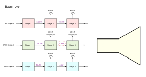
If we look at following example, stage 2 is most likely the problem area. I used "most likely" because one must allow for the lessor-likely possibility that a problem at the front end of stage 3 is loading stage 2. With stage 2 identified, you then do comparisons within stage 2, compared to within stage 2 of one of the other channels.

Some related safety/hazard information is at [here].
1714260362560.png

I am using Sam's guide and have followed these sections:

"MAGENTA (NO GREEN): Check Chroma and Green Output circuits. Refer to "Troubleshooting" Raster circuit.

Raster is magenta (No green). Check voltages, waveforms
and components associated with Transistors Q535, Q534,
Q532, Q533 and pin 4 of the CRT socket."
Are you saying that all of the 'green channel' voltages up to and including the CRT socket are as expected ?
 
I am using Sam's guide and have followed these sections:

"MAGENTA (NO GREEN): Check Chroma and Green Output circuits. Refer to "Troubleshooting" Raster circuit.

Raster is magenta (No green). Check voltages, waveforms
and components associated with Transistors Q535, Q534,
Q532, Q533 and pin 4 of the CRT socket."
Pin 4.
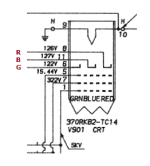
Conflict: Earlier in the document is the circuit diagram, and that diagram shows pin 6 for the green channel cathode.

1714261842537.png
 
I should have titled this as the green channel has failed. That's a better description of the actual issue.

I am taking all precautions. I discharged the tube using a screwdriver with an alligator clip attached to ground before I do anything. I make sure to do this after any time I have powered it on.

The quoted section on raster troubleshooting is right out of Sam's guide. This does appear to be wrong.

I have not measured any voltages yet. I can start there next. That seems like the next logical place to start. I was mainly looking for any failed capacitors, BJT transistors on the green line (just a diode test in circuit nothing more), and anything else that looks to have visibly failed. I have not found anything that has failed yet.

The conflict of Pin 4 of the CRT socket in the troubleshooting section vs Pin 6 on the diagram is a good find. Pin 4 is right out of Sam's document under "troubleshooting" for locations to check, but I didn't realize that it didn't match the diagram. This seems to be an error.

There are only 10 physical pins. I think it counts 12 total with 2 being not connected since there are 2 blank spots on the socket.

The socket itself has labeled the pins thankfully. It starts at pin 4 as the first pin after 1. I'm guessing that there is no pin 2 or 3 since the next labeled pin is 4 after pin 1.

I left the socket unplugged and measured the DC voltages with the tube itself unplugged from the board. The values are a little high. That might be because the tube itself was unplugged, but it gives me a starting point.

1 - Not touching since it's 5KV. My meter is rated for 1KV.
2 - N/A
3 - N/A
4 - 0
5 - 43.1
6 - 149.7
7 - 318
8 - 145.6
9 - 0
10 - 0
11 - 144.6
12 - 0

Pin 6 did read a voltage surprisingly. I was expecting it to be 0 since there is no green.

Tomorrow I'm going to see if I get better readingings with the tube fully plugged in and the grounding wires re-soldered. The pins can be measured from the back of the neckboard. It's re-labeld as KG, KR, and KB on the back. If these still all check out as too high I will finally have found something that's wrong!

KG - Pin 6 Green
KR - Pin 8 Red
KB - Pin 11 Blue
 
With a bit of adjustment, I have red and blue dead on, but green does not go lower than 130V. That with the knob at the max.

I did notice B+ was at 113V so I did adjust it to 115V where it should be.

I was thinking that Green Drive might be too high, but it doesn't seem to make a difference if it's all the way up or down. I left it at mid-range.

The Screen Adjustment I didn't touch it yet since it's glued in place. I believe this is only for the screen brightest through.

KG - Pin 6 Green - 130V
KR - Pin 8 Red - 126V
KB - Pin 11 Blue - 127V
 
Back at post #1, I see that at some point in the colour alignment, you did see green.

Over the years, it appears that something in the green channel has deteriorated slightly. You eliminated the CRT. Given that you did see green back at post #1, I think you should be able to compensate for the deterioration by adjustment.

I will bring out my 5153 later in the day, and see if it is normal to get the cathode voltages down to the 120V level, because rather than compensation-by-adjustment, you may want to find the root cause. Maybe go for compensation-by-adjustment, and if the display doesn't look quite right, then go hunting the root cause.
 
I think it's a failing resistor, diode, or transistor on the green line that has not completely failed yet. The lowest I can get the green line down to is 130V. The adjustments on red and blue drop-down to 80V and the top is around 200V. Green just won't go that low.

It gets very close when I have dropped the green line all the way down to 130V. At this point, the screen is almost white like it should be, but I can see green raster lines going across the screen.

I think it's something that has half failed or is going out somewhere on the green line. I can check more thoroughly now that I have a good way to tell if anything has changed or not.

I was hoping the Green Drive would bring the voltages back down, but as far as I could tell it made no changes.
 
KG - Pin 6 Green - 130V
KR - Pin 8 Red - 126V
KB - Pin 11 Blue - 127V
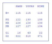
I have measured mine with no signal in. Let's compare yours to SAMS and to mine.
1714380236684.png
So, right there, we know:
- From my KG/KR/KB, that the problem with yours is not that KG cannot be adjusted below 130V.
- From SAMS KG/KR/KB and my KG/KR/KB, that there can be quite a range or working voltages.

Your G1 seems to be quite high, but I expect that to affect all three colours.

I was hoping the Green Drive would bring the voltages back down, but as far as I could tell it made no changes.
The GREEN BACKGROUND pot (on the neck board) impacts on the KG voltage as well. On my 5153, with no input video signal, and both the GREEN DRIVE and GREEN BACKGROUND pots at the fully clockwise setting, KG got down to about +65V, and the screen was bright green.

Try this very crude alignment (which works reasonably well on my 5153).

1. Have a video signal coming in. I had a DOS prompt up.
2. Set front-panel brightness control to about the 3/4-range setting.
3. On the main board, set the GREEN DRIVE pot to about the mid-range setting.
4. On the neck board, set all three BACKGROUND pots to the fully counter-clockwise setting.

At this point, the screen should be completely blank.

5. On the neck board, turn the BLUE BACKGROUND pot clockwise, until the raster (raster - ignore the text) (raster will be blue) just appears, then back off the pot slightly until the raster disappears.
6. On the neck board, turn the RED BACKGROUND pot clockwise, until the raster (raster - ignore the text) (raster will be red) just appears, then back off the pot slightly until the raster disappears.
7. On the neck board, turn the GREEN BACKGROUND pot clockwise, until the raster (raster - ignore the text) (raster will be green) just appears, then back off the pot slightly until the raster disappears.

At this point, you have text on a black background. The text may or may not be the desired white (technically, light grey). If not white, adjust the DRIVE pots accordingly.


Does that work ?
 
Don't get too caught up on making the cathode voltages match the schematic exactly. They will vary slightly depending on the condition of the CRT.

An oscilloscope would be highly useful here. I would start at the green video input pin, and follow the signal until it stops. If you can't do that, then DC voltage checks may be enough to find the problem.

Unless you are going to remove the HV connector, you don't need to discharge the CRT.
 
A bit more testing. I followed the Color Temperature Adjustment section in Sam's guide. The Screen Adjust (Listed G2 in some places in the guide. There is a screen label in the actual monitor below the focus knob.) was glued in place so I had to break that seal to get it turning again.

The guide says to set Green drive and Blue drive to mid-range, switch to service mode (this sets a line on the screen and nothing else), adjust the Screen Adjust until a dim line is visible, adjust the background red, blue, and green from minimum until the line is white, switch back to normal mode, adjust Green drive and Blue drive to get to white and black.

I followed this guide exactly and found that the settings were pretty much the same as before I started. I can get a white line, but out of service mode, it's back to all magenta. If I max out the green background (which voltage-wise is the lowest possible voltage of 130V) I get back to almost white, but green raster lines are 100% visible. Even with a small turn back down it's back to fully magenta once the raster lines disappear.

Most importantly I found the Green Drive to have no effect on the amount of green on screen. The screen did get brighter when adjusting Green Drive but was still purple. Blue Drive did make the screen more blue as expected.
 
I know you can make the screen light up green, but is there any actual green video in the picture? It sounds like there isn't. Assuming that's the case, then something is interrupting the green video signal. You're not going to adjust your way out of it.

Luckily, there are three identical video circuits, so you can compare voltages, and signals between them. Start at the the green video input from the video card, and go step by step until you find a discrepancy. The schematic shows voltages, but if something seems off, you can compare to the red, or blue.
 
Most importantly I found the Green Drive to have no effect on the amount of green on screen. The screen did get brighter when adjusting Green Drive but was still purple.
On my 5153, with no signal in, the raster being displayed, GREEN DRIVE greatly varies the raster colour.

The guide says to set Green drive and Blue drive to mid-range, switch to service mode (this sets a line on the screen and nothing else), ...
The service switch also disables video: disables vertical deflection and video.

I followed this guide exactly and found that the settings were pretty much the same as before I started. I can get a white line, but out of service mode, it's back to all magenta.
That last sentence is interesting. The 'disable video' half of the service switch connects to the GREEN DRIVE area of the circuitry.

I am sure that you do not have an oscilloscope, because I am sure you would have mentioned it. You have a multimeter.

If we go back to the image in post #2, you have two 'apparently good' colour channels to compare the green channel to, using a multimeter. And you have the SAMS document as a reference.

Re the SAMS document. The DC voltages (and waveforms) written on the circuit diagram are for when there is a CGA signal coming into the 5153. The recorded DC voltages are a guide. There will be variations between 5153's, some large (e.g. due to other settings). You need to concentrate on your green measurements compared to either red or blue. (Blue is good for me because a RED DRIVE pot does not exist.)

Based on what you have observed so far, I think that the base of transistor Q533 ('GREEN DRIVE') is a reasonable place to start. With the service switch off: When you adjust the GREEN DRIVE pot, the average DC voltage at that point is expected to vary. How does that compare to the equivalent transistor in blue? Ignore what you see on the screen.
For example. On my 5153, service switch off, and no signal in, adjusting GREEN DRIVE from one extreme to the other, I see a variation of 1.6 to 3.1 Vdc on the base of Q533. Moving to blue, the base of Q503, I see the same variation (1.6 to 3.1 Vdc) adjusting BLUE DRIVE.
 
I do have an oscilloscope. It's one of those one's built into a multimeter so it's not the best.

I will follow along the green line and compare it with blue/red. I think that's my best bet at this point.
 
FYI.

After finishing off some small projects, I returned to my 5153. It needed the colour balance realigned following experimental adjustments that I had made for this thread.

I set the front-panel brightness pot to about the 3/4 position, fed in a CGA signal, then proceeded to do the 'COLOR TEMPERATURE ADJUSTMENT' section of the SAMS document.
Some notes:
- On my 5153 (repeat: my 5153), when I increased the screen pot to get a line-across-the-screen just showing, that line was predominantly green.
- And although the service switch did remove vertical deflection, it did not remove video on my 5153. I could see the vertically collapsed POST errors on the far left. I just ignored that part of the line.
- Accordingly, with green predominant, the RED BACKGROUND and BLUE BACKGROUND pots were the ones I then adjusted. (Per that sentence in the instructions, one of the 'background' pots is not adjusted at all, and for my 5153, that was the green one.)
- I did not need to execute the final sentence, because on my 5153, the text was already white.

Good/correct colour balance then verified using the video test in CheckIt software.
 
Glad to have it confirmed then. It's something on the green line.

I will follow up when I find more time to trace it out and find what is off.
 
Back
Top