• Please review our updated Terms and Rules here

I am repairing an Apple IIGS RGB monitor, A2M6014, and need your help.

jk92

Member
Joined
Jun 27, 2023
Messages
16
Hello. I got this monitor, A2M6014, yesterday and I have a problem with it. The seller said it is working fine but it actually is not.

What I can tell is that the screen scrolls left to right constantly and rapidly.

There are three adjustable knobs in the back, V-HOLD, V-HEIGHT, H-HOLD. First two seems normal, it doesn't really help with the situation but they seem to be doing their job.

But then I turn the H-HOLD knob, it gives me very weird symptoms.

When I turn it to clockwise, the screen gets darker and darker as if I am turning a brightness knob and eventually I cannot see anything.

If I turn it counter-clockwise, it makes the screen brighter and when it reaches to the end, the monitor turns off. With that position, I cannot turn on the monitor back. No power no nothing.

I have to move the knob to around the center to power on the monitor.

I measured the resistance for the pot, VR502, and it shows around 4.5k ohm. The monitor schematic shows 5k so it is okay I guess?

That means something else is the problem but I do not know where to start.

Please share your knowledge with me. Thank you.
 
Does the IIgs drive another monitor correctly? (I'm assuming you know the IIgs is good.) If so, then it sounds like the monitor has a failed component in the horizontal circuitry somewhere. Have you opened it up to look for obvious capacitor failures?
 
I do not have any other monitor for IIgs but its composite output works fine with my TV. It reads floppy disks, goes to OS screen. I really wish I can hook it up with my VGA monitors but connectors are totally different.

Inside the monitor is surprisingly clean. No dust at all. As far as I can tell, there is no leaking capacitors. Well, at least not visible from their top side.

There are several pots that need a screw driver to turn and they all do nothing much.

I am curious why H-HOLD controls the brightness. Does “normal” IIgs monitor do that too? Probably not. I will post some pictures videos later.
 
Part of the reason for the H-Hold's behavior is that the horizontal flyback transformer also generates the high voltages the CRT requires (B+, screen, focus, etc.)

The monitor shutting down when it gets to a certain point means the high-voltage shutdown circuit is engaging (as it should - prevents the CRT from becoming an X-ray generator).

The issue seems to be either the V / H sync pins are not making a connection or there is a failure in in the horizontal oscillator / sync stage.
 
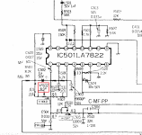
Yes, I've downloaded the schematics. The red box in the picture shows the pot for H-HOLD.

resistor.png

If I really try to fine tune the pot, I am able to get a readable screen but still moving as you can see in the video.


I've tried 3.3k ohm pot but no luck with it as well. I guess the problem is something else as you guys mentioned.

Honestly, I cannot find what and where the oscillator is and it is not easy for me to understand the schematic.

What should I look for now?
 
I'll need to look over the schematics and the data sheet for the LA7822 chip further.
One quick thing to try, see if any adjustment of the horizontal centering control helps to achieve lock on the horizontal hold (but I'm thinking it might not help).
Do you have a capacitance meter? Unsolder C502 (keep a record of where the - lead is) and check its capacitance (1µF). Do the same for C519 (22µF) (don't forget to discharge it before touching both leads). While C502 is out check the resistance values of R505 (2.2k), R506 (47k) and R507 (12k).
 
The Apple II Family Service Procedures vol 2 has a section that covers this monitor (p 385-453). Note that Acrobat Reader has real problems with this file, I had to use Okular on Linux to view it. It says that if the horizontal hold is adjusted too far out of range it will shut down, as you have observed. The corrective action is to turn off the monitor and place the horizontal hold adjustment back to center position. Not much else useful in the troubleshooting section other than to say replace the main board and/or power supply board. Since you do get an image displayed with reasonable intensity and area the power supply board is probably good. Thus you'll have to diagnose to the failing components on the main board.
 
Your missing horizontal sync. Video comes in IC501 pin 14 and there is an internal sync separator. The standing vertical floating bar means the horizontal is the correct frequency, just not sync'd.
Maybe C501 is open ?

Larry G
 
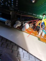
hcenter.jpg

The Horizontal Center does not really do anything. It moves the screen a little bit but nothing else.

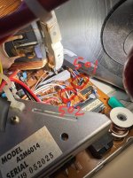
cap.jpg

I found C501 and C502 deep inside the board. I have no access from the back because plastic housing is blocking them. I have to take the whole board out in order to unsolder them.

However, I just checked their value while they are still in position as seen on the picture. C502 gives me 1µF as expected. Now, C501 on the other hand, gives me a value of 0! No nothing.

I don't know it is because I am measuring it while it is sill on the board but definitely suspicious. I might have to remove it, check the value again, and replace it with 1µF 50v cap I have.

Take that board out of the metal housing will be a challenging job for me. Wish me luck!
 
As for C502, there are effectively four resistors across it, so they would affect the reading in circuit. If you unplug the connector that runs to the H Hold pot, you would break that loop and maybe could get a measurement.
 
Sorry, I have been busy lately. So I did replace C501, C502, C509 but no luck. They all are actually have good values when I removed them from the board though.

Nevertheless, I replaced them all and still no good.

I also measured many of the resistors connected between the pot and LA7822. Most of them are okay, some of them have a little off values but I guess they are all okay.

Now, I suspect the LA7822 chip and I've ordered 2 of them from Ebay. I am going to install a socket and try them. Probably it works? I am not sure.

Btw, I made a custom cable to connect my old Sega Genesis to the monitor and it looks fantastic. Yes, the screen is still scrolling horizontally but I can make it still briefly as you can see on the video I uploaded.

I really wish I can fix this thing up and use it for my old game consoles.
 
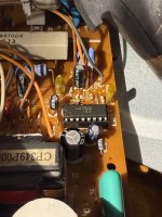
So I've installed a socket and a new LA7822 chip. Sadly the result is exactly same.

IMG0000.jpg

I unsoldered C501, C502, C503, C519, C520, C531, C513, C504, and R502. They all have correct values.

Also measured R501, R502, R503, R504, R505, R506, R507, R508, R509. Most of them are okay with slight lower or higher values.

Not sure what to do next...
 
you need an oscilloscope to check for video signal coming into pin 14 and sync out of pin 12.
D512 is also a possibility.

Larry G
 
Last edited:
I checked the pin 14 and it gives me 12V and around 15.74 khz. On the other hand, pin 12 is almost 0V so that I cannot even measure the frequency.

Very weird because I've tried 3 different LA7822 chips including the original one. I measured pin 12 directly from the chip. What could it possibly affect in the readings?
 
My mistake. Pin 12 is not even used here. If you look in the schematic above IC501 there are pins marked VD and HD. We are only concerned with HD since the vertical is locked ok
(not rolling up/down). Pin 12 feeds pin 11 which is vertical section but pins 7,8,9 are not even used. VD goes straight to IC401 so let's forget that path, However, if you look at the schematic
with the 15 pin dsub connector, pin 3 contains both HD and VD sync signals (composite) which feed Q605 but only HD comes out of Q607 so it is possible that transistor could be bad. Pin 4 of connector C2 is HD
which should read 15KHz and maybe 3 or 4 VDC. This is going to get hard to understand but since you already measured 15KHz present at IC501-14 then the only missing factor is sync (POLARITY). According
to the LA7822 data sheet, pin 14 is positive going video which means negative going sync. One thing Q607 does is INVERT the sync polarity. If Q607 was open B to E the sync will pass thru wrong polarity. I would
check Q607 next.

Larry G
 
I've measured the Pin 3 and Pin 4 of connector C2 and both of them shows 15.72khz.

I also tested Q607 transistor marked 603, and it looks normal. I unsoldered it, tested it with my multimeter, shows okay.

D512 is unsoldered and tested, it is working.

Maybe I should get another A2M6014 to compare. lol
 
Actually I have a working A2M6014 but also have a VidHD card for my 2gs so use an LCD most of the time. I could take some scope readings but that means you would need to compare with a scope as well.

Larry G
 
Thank you so much for your offer. I will try measure and upload some pictures.
 
Back
Top