• Please review our updated Terms and Rules here

Model I Power Adapter Specifications

GCM

New Member
Joined
Oct 12, 2009
Messages
2
Location
Austin, TX
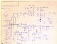
I'm a restoration engineer at the Goodwill Computer Museum in Austin, TX. We need to bring a TRS-80 Model I back into operation to recover some data from stringy floppies for the digital archiving program at UT. Unfortunately, the Model I we have does not have a power adapter. Can anyone point me to specifications for what voltages it outputs? I found a schematic for the Model I that seems to show AC coming in to a rectifier bridge, but no indication of what voltage, plus something coming in on the middle pin for purposes unknown. Any help would be appreciated.
 
The original Radio Shack Power Pack has a transformer with dual secondary windings. One winding is rated at 17VAC with a center tap and indeed does feed a bridge rectifier within the Model 1. The other winding is also center tapped and feeds two internal diodes for a full wave rectified output. The voltage of the rectified output is 9 Volts. This information was obtained from the schematic of the LNW Research Expansion Interface kit.
Scan attached.
 

Attachments

  • TRSMOD1PS.jpg
    TRSMOD1PS.jpg
    92.7 KB · Views: 1
Thanks

Thanks

Thanks. That helps a lot. We should be able to cobble something together that will get us up and running.
 
If you're going to recover the stringy floppies, I highly suggest you bake them first. Someone else on here tried recovering theirs without baking and the tape was quite sticky and jammed up in the drive.

Do some research into tape baking. It will temporarily restore the tape long enough to recover your much-needed data.
 
The original Radio Shack Power Pack has a transformer with dual secondary windings. One winding is rated at 17VAC with a center tap and indeed does feed a bridge rectifier within the Model 1. The other winding is also center tapped and feeds two internal diodes for a full wave rectified output. The voltage of the rectified output is 9 Volts. This information was obtained from the schematic of the LNW Research Expansion Interface kit.
Scan attached.

Hmmm, the detail on the bottom of my R/S power pack shows the outputs as:
pins 2-4 19.8 VDC .35A
pins 1-3 17.0 VAC 1.0A

It would be nice to find a couple of these for spares...
<*> Jim
 
Jim,

You are SO right! I dug the drawings out again and looked really close. The drawing's I have are old amonia blueprint copies of the original. Very close inspection shows that there is a 1 hidden before the nine and 7 following the 9. These are what I thought were artifacts of copying process. Following the circuit out, it would be hard pressed to get the +12v supply from a 9 volt source. I'll need to check things out a little closer before posting..
 
Back
Top