The circuit is just a half-adder (it has 2 inputs A & B but no Carry bit in, and 2 outputs, the SUM of A & B, and a Carry bit out)
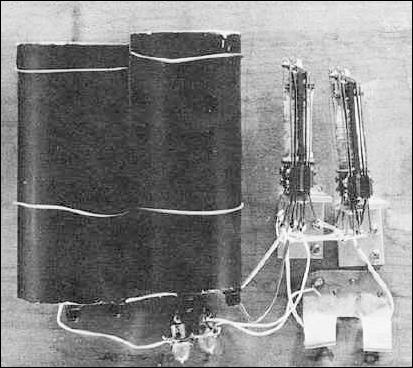
If you aren't familiar with circuit diagrams etc... the relays are in each of the red boxes. the magnet is the square, and the double-throw (relay) switches are shown in the "normal" or magnet-switched-off position. when the magnet is energised, the ganged (shown by the dotted line) switches (arrows) move together to the other contact (circle)
You can construct a truth table for each of the 4 states that the inputs can be, ie 00, 01, 10, 11
then you get an answer for the SUM output that says "when only one input is on, the output is on" i.e. an exclusive-or function.
you get an answer for the Carry which is when bits A and B are on, an AND function.
The rest is just bulbs and batteries stuff, The AND function for the carry is two switches in series which must both be on for the light to light,
and the EXclusive OR is rather like 2 way light switches, both switches have to be in opposite states for the light to come on.
when you start to think further down the line, the input switches can get replaced by relay contacts from a previous logic gate, and the lightbulbs can be relay coils for a later logic gate, which is how the system joins together.
relay logic is dead easy on one level, because an AND just has contacts of each relay in series, an inclusive OR has them in parallel, an inverter has contacts that are closed when the relay in't energised, and open when it is.
The fun really starts when you add delays to relays with resistors & capacitors, and use bistable and current sensing ones. I was lucky, I had loads of them to play with when I was a kid, because my dad was a railway signalling engineer.