• Please review our updated Terms and Rules here

Need Schematics and Photos of an Alspa ACI-1/2 Power Supply

DistantStar001

Experienced Member
Joined
May 8, 2019
Messages
178
I got an Alspa ACI-2 a few weeks ago thinking it was just a dual 8 inch floppy enclosure, only to discover it was a full CP/M computer. Unfortunately, the main power supply had been stripped, and the most of the case screws are missing. However, as luck would have it, I managed to find the missing power board and transformer on eBay. Just one problem... I have no idea how to connect them.

It looks like both the original and replacement PSUs had been cut out of their respective units, but not necessarily in the same ways. As such, I'm a bit confused as to what goes to what. So I was hoping that someone out there would be willing to take some pictures of their units' inner connections? Specifically of the power port and fuse to the main transformer. Alternatively, the schematics? I'm not great at reading them, but power issues are usually pretty straightforward. Basically, I just need to see how this all fits together.

At the moment, when plugged in the fan goes, but unsurprisingly, that's it. The fuse is good, and the motherboard, case, and drives all appear to be in good condition. But obviously, I can't be sure until I can turn the whole thing on. Any help, documentation, advice, or general info about this computer would be appreciated.

Side question, and I know this is down the line, but from what I can see, this was meant to interface with a dumb-terminal, and all I have is an ICOT that connects via coax, and needs proprietary software on the server side. I do have a few IBMs and Apple IIs with serial interfaces, but I think I'll need a terminal emulator to connect them. Alternatively, I do have a terminal emulator for the VIC-20, but that lacs the proper serial port. So assuming I will be unable to get a proper terminal, what do I need to get the ACI to interface with either an Apple II, or IBM 5150, or 5160? Or failing that, a modern computer with serial to USB adaptor?
 
Well, since no one else has answered yet, I'll suggest you might need to reverse engineer the missing bits.

You can usually trace the rail inputs and requirements on the board to figure out where the power goes and what goes where. There should be a single connector where it goes in. I've seen multiple connectors before, but it's very rare for that to happen.

Then power up your PSU and see what it puts out. Then map between the two. Some early PSUs required a load to work properly, but again, that wasn't all that common. Don't forget to make sure you've cleaned up any parts of the PSU that need work - :)
 
Alright, so taking all the advice here.
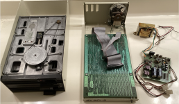
To start, this is what I have:
Screenshot 2023-11-29 at 22.05.03.png
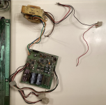
Here is the power supply and internal connections:
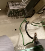
Screenshot 2023-11-29 at 22.04.24.pngScreenshot 2023-11-29 at 22.04.37.png
I was able to trace the mains to the two pins under the fan with the green wires soldered to them. One of those wires is soldered to the transformer under the fan via the twist connection in the bottom right of the picture. There also appears to have been a red and a black wire soldered into the connection that was cut (probably from the original power supply). The other green wire goes to the switch, and from there is soldered to the transformer under the fan.

The main PSU transformer appears to be putting out at least two voltages divided between the upper and lower coils. I'm assuming that the output wires are soldered to the PSU board. The input wires (again assuming) are divided between the brown and (what was) white, and the red and black. Both pairs are soldered into their respective twist connection. However, the black and red connection has a second black wire going to a female two prong connector with a red wire that isn't connected to any thing. Originally, I thought this was a mains-in connection, but the wires are kinda thin for it, and I'm not entirely sure what it was supposed to plug into.

In all likelihood, the PSU I have is from a different revision. I have no doubt that it can be spliced in, the question is how? Understandably, I don't want to plug it in until I know it's correct. 115 volts is just something I don't want to mess with.

I'm messaging "Glitch" now.
 
Last edited:
Seems the power from your PSU is as follows

BLK - GND
BLK - GND
GRN - (-5v)
RED - 12v
WHITE - 5v
WHITE - 5v

It's written next to the wires. Though it's what I would have guessed.

Power up the PSU and check these voltages are accurate ( within 0.2 v ) and are all present. It also means your PCB probably has 4116 RAMs so be careful. It's a likely situation that one or more is faulty too.

That 6pin connector is probably the board PSU. The two large connectors most likely go to the back of the disk drives.

I have no idea where the switch is.

You can check which side is GND and which side is 5V based on where they go to on chips, with a multimeter.

Then you probably just plug it in and power it up. ( After making sure all the voltages are accurate and present ).

Regards
David.
 
Also the smaller ribbon cable looks like it goes to the pin header on the power PCB. I'm not sure which way it goes around. You'll have to reverse engineer that if it's not marked somewhere.

The ribbon cable would be for communications ports. They may also take additional voltages from the PSU to drive the signals, but most likely the 25 way connectors we can't see are probably just only connected to the pin header. They would be designed that way to stick out the back when the PCB is mounted.

David
 
Alright. I'm pretty sure that I got it connected right. At least to the main 115v. Even though it started spitting smoke. I'm saying this because, before it started smoking, the I was getting -5v on the green and +12v on the red. White was giving +10v... So something was wrong. Then, on the next test, I was getting nothing. No voltage. Nothing!

The smoke only started when my probe slipped on what I'm guessing was the 12 regulator. So I probably shorted it. Not the end of the world, and for a 40-something-year-old power supply to be a bit dodgy is understandable. My plan is to replace the burned out (I'm guessing) regulator and whatever's responsible for 5v. I'm also thinking of testing all the capacitors.

The good news is that I did not plug this into the motherboard, so technically, this is as functional as the day I got it.
 
Then the +12v and -5v are critical just as much as 5v...
You can get a small switchmode that will replace it pretty cheap... You'll need to keep the PCB to distribute the serial so hopefully you can fit a small one in the top. As a thought, you can get a laptop-connector to +12, -12, +5, -5 for the ATX PC Connector pretty cheap and they are small, so would make a good replacement and keep the high voltages out of the case and let you remove the transformer... And you can always repair the PSU later to keep it original.

There's a good chance the RAM is faulty too. But you won't know until you power it up... And you'll need to monitor the serial port for activity.

But powering it up is a first step, then feel for any RAMs that are warmer. ( Faulty 4116 RAMs are often a bit warmer ).

If you have a lab PSU, limit the input current to around 1 amp at first so that if there's any shorts or shorted chips, a modern PSU doesn't just fry the whole board.
I've been looking into this, but I think I also need +24v and enough amps to run the floppy drives. From what I understand, it doesn't boot to BASIC. It needs a floppy. Also, to test the RAM, I'll still need a dumb-terminal as there is no direct video or display out on this thing. It's really a weird little computer, but it's proving to be an interesting puzzle to fix. Still, if anyone has the schematics, I'd really appreciate it!
 
Back
Top