• Please review our updated Terms and Rules here

Would appreciate help on Screen full of 0i's

11132Downing

New Member
Joined
May 7, 2024
Messages
8
Hello: I am totally new to this forum and don't fully understand the rules of how to start asking for help -- other than yell HELP. I have a TRS80-M1 that produces a full screen of 0i over and over. I have lots of details I can share but first I need to make sure I am going about asking for help in the right way. Thanks Jim
 
First step is to scope out the video divider chain. Some of the frequencies created also control other things. I did a video of a similar repair a few weeks ago. Note the section where I pulled the RAM config jumpers to note any difference in behavior.

 
You can remove the X3 plugin (just make sure you know how
it is oriented) and the display will be filled with @9@9@9@9.
If it has something else post a photo of what you see.

Larry
 
You can remove the X3 plugin (just make sure you know how
it is oriented) and the display will be filled with @9@9@9@9.
If it has something else post a photo of what you see.

Larry
Larry: Thanks for the input. Unfortunately I have removed X3 and did not get the @9 full screen. Let me describe my situation:
1. I have 2 M1 computers. One works fine (#1) and one used to work fine (#2).
2. I just got #2 working and was about to button it into its case but decided to add the l-case patch. While doing so, I screwed something and have not been able to figure out what I did.
3. All of the divide chain frequency and amplitudes are perfect.
4. The screen is full of Oi or Oy. Sometimes starts and stays with Oi and other times starts with Oy. See attachment. I only have 1 operational RS monitor so I hooked #2 to a modern monitor.
5. I changed out all the video RAMs and removed the double layered 2102 that I built while trying to do the lower case mod.
6. I changed out all the ROMs. This, nor 5, had any affect on the screen of Oi's
7. If I remove the character generator (Z29) the screen is filled with vertical rectangles (some have suggested squares but mine are rectangles that fill each full character space)
8. I put a scope on all the address lines coming out of z38, 39, 22, and 55. All are active pulses at about 4v amplitude. None stuck high or low.
9. The only thing that I have found fishy is the pulse coming out of z30-13 going into z60-4 and z27-13. This is the fake bit 6. In the attachment the green trace was taken a z30-13 (output) and the yellow at z30-12 (pulse side input). Clearly the output side of the NAND is pulled down by something.
10. Since I cut the trace connecting z30-13 and z27-13 I scoped the same two pins on z30 to get the second scope image. Here you can see that the NAND did exactly what it was supposed to do when the load was removed.
11. What was killing the NAND output? Since I had some LS367's I replaced z60 thinking it might be the culprit as it was involved in my lower case attempt. The new chip did not change anything. The only other connection is flip-flop z27-13. I am waiting for some 74LS175 to be delivered. If I do a scope comparison pin-by-pin between computers #1 and #2 on z27 all seems reasonably comparable except for this low output from z30 on z27-13.

I will gladly make other measurements if that will help. Please let me know.

I have read about how some of you guys can look at the characters on the screen and somehow map that into faulty RAMs. I have tried to understand how that is done but have not mastered that skill. Maybe someone can explain the process.

Any assistance will be greatly appreciated. Thanks
 

Attachments

  • screen issue.jpg
    screen issue.jpg
    336.4 KB · Views: 10
I haven't had time to plow through your text, trying to follow your directions. I'll try to
get to that soon.

What Lowercase Modification did you follow? Here is what I suggest. Look at the
attached Photo and re-trace your connections using the attached photo. OHM out
each pin for the changes as marked for the IC at Z45A. When you get to Pin 13 of
Z30 it needs to be CUT (MARKED IN RED) so that output does not go to Z60
Pin 4 and to Z27 Pin 13.

That should complete the Lowercase Modifcation and make it functional. If you find
any other traces cut or jumpered to anywhere else they need to be repaired and/or removed
so your finished motherboard matches that attached Photo.


Larry
 

Attachments

  • Model-1_Lowercase_Mod-Correction.png
    Model-1_Lowercase_Mod-Correction.png
    332.8 KB · Views: 3
9. The only thing that I have found fishy is the pulse coming out of z30-13 going into z60-4 and z27-13. This is the fake bit 6. In the attachment the green trace was taken a z30-13 (output) and the yellow at z30-12 (pulse side input). Clearly the output side of the NAND is pulled down by something.

Z30 Pin 13's trace to Z60 Pin 4 and Z27 Pin 13 needs to be CUT (removed from Z60 Pin 4 and 27 Pin 13) so
the New A45A Video Ram works properly. It appears you have cut the PCB trace at a random place and did
not OHM point to point making sure the proper trace was cut.

It shouldn't take but a few minutes to retrace the NEW Z45A and connections from Pins 11 & 12 to
Z60 Pin 5 and Pin 4. You also need to VERIFY the connection from Z60 Pin 4 to Z27 Pin 3.
IC Z30 Pin 13 is cut, so it doesn't go anywhere.

That should fix your problem.

Attached is a Photo of the exact PCB Trace to cut.


Larry
 

Attachments

  • Z30-Trace-to-cut.png
    Z30-Trace-to-cut.png
    103 KB · Views: 5
Last edited:
Larry Thanks for your reply. The modification you described is basically the Electric Pencil mod without the switch. What I have is the switched version. The cut between z29 and z30 as you illustrated was made properly and has a pair of wires (one on each side of the cut). I understand how to implement the mod but somehow I messed up something to make the screen fill with Oi's instead of the @9's that it should under the circumstances I described in my original post. Maybe z27 is bad and killing the pulse from Z30-13. I am still interested in learning how to interpret the Oi's on the screen and how they are generated.

Jim
 
First step is to scope out the video divider chain. Some of the frequencies created also control other things. I did a video of a similar repair a few weeks ago. Note the section where I pulled the RAM config jumpers to note any difference in behavior.

Jeff I would like to view your post but it just gives an error message when I try to run it. When you pulled the jumper I gathered you got a screen full of @9. I pulled the jumper and got a screen full of Oi. Is there some magic scheme for interpreting this and how its possible cause? Jim
 
Larry Thanks for your reply. The modification you described is basically the Electric Pencil mod without the switch. What I have is the switched version. The cut between z29 and z30 as you illustrated was made properly and has a pair of wires (one on each side of the cut). I understand how to implement the mod but somehow I messed up something to make the screen fill with Oi's instead of the @9's that it should under the circumstances I described in my original post. Maybe z27 is bad and killing the pulse from Z30-13. I am still interested in learning how to interpret the Oi's on the screen and how they are generated.

Jim
Larry Back to the Lower Case issue momentarily. You suggest I should use the switchless Electric Pencil mod. However, the character generator I have is 6670 and I have read that simple mod will not work with that chip and that I would need to use the one described in Custom TRS-80 and Other Mysteries. Do you agree or is it possible to use the simple mod you suggested. JIm
 
The Mod I used and suggested is for the 6673 Character ROM. I don't think I have the Electric Pencil mod in my
stash of documents.

Larry
 
Is there some magic scheme for interpreting the characters that are displayed?

I see this when the system starts:
MMMORQ SAZE?


The E & Y & A characters are incorrect.
M = 0x4D = 0100 1101B versus the correct Character E = 0x45 = 0100 0101B ALSO Bit 3
Q = 0x51 = 0101 0001B versus the correct Character Y = 0x59 = 0101 1001B ALSO Bit 3
I = 0x41 = 0100 0001B versus the correct Character I = 0x49 = 0100 1001B ALSO Bit 3

Bit 3 is Z45 of the Video RAM.

Larry
 
I'm thinking that you can't do the @9's test with your 6670 Character Generator
since the first character is the Large Square Character. But, the address of 39
doesn't match with the Capital "I". That could indicate another problem with the
Data Bus.

What about trying the 6673 Character ROM? I know it works well with the Model 1.

Photo Attached of the Character at Location 0x00. (It matches your posted Photo.)


Larry
 

Attachments

  • 00.png
    00.png
    2.8 KB · Views: 1
Yeah, that's not a zero, it's a box character, if it's 00, then it would be the same as the @ without a lowercase mod. The lowercase "i" should be 69, but the "9" is 39. I'm not sure how to get the high bits to match with 69 vs 39, but it's not far off from @9.
 
Here are the Characters in MCM6670 & MCM6673. As you can see the Character at address 0x00
and 0x38 are a bit different. How the Stack is written to eventually overwrite 0x3CFF to 0x3C00
is described on the Google Groups on March 11, 2003.

March 11, 2003

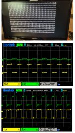
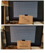
> I've just remembered, one of the tests in the techref is to pull the
> ROMs and see what happens - you should get a screenful of @9s that
> flicker as the CPU tries to access the ROMs....that's exactly what I
> get so the CPU MUST be running at that point.

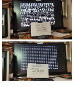
It helps to know that. Here's why you get @9s. With the ROMs removed,
the CPU reads all 1's (that is, hex FFH) whenever it reads from the area
the ROMs are supposed to be in, because an open connection tends to
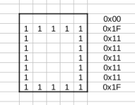
float to a 1 with this type of logic. Hex FFH is the RST 38H
instruction. So when the processor is turned on and fetches an
instruction from 0000, it gets a RST 38H (FFH). This makes it push 0001 on
the stack and jump to address 0038. At that address it reads another
FFH, so it pushes 0039 on the stack and jumps to 0038 again. Now it's in
an infinite loop. As the loop continues, the stack grows and grows,
going backward through memory. When it reaches the frame buffer between
3C00 and 3FFF, you can see it on the screen. It looks like a string of
@9's because the TRS-80 displays a 00 byte as an @ character, and 39 is
an ASCII 9.

OK. So the fact that you get @9's means that the CPU is working. The
data bus appears to be working correctly too, as if a data line were
stuck at 0 the CPU wouldn't be reading FF's, and if it were stuck at 1
the CPU couldn't be writing both @'s and 9's.

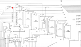
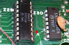
There could still be a problem with the address bus or the ROMs. Note
that a problem with the ROMs might not be in the ROM chips themselves
but in the sockets or circuits on the motherboard that connect them to
the rest of the system. But trying a different set of ROMs does seem
like a good idea.


pc 0000 gets FF pushes 0001 to stack jumps to 0038
pc 0038 gets FF pushes 0039 to stack jumps to 0038

The problem I see is the 0x0038 you should be getting is either 0x0069 or 0x0079. (The "i"or "y")
on the Data Lines.

0x0038 = 0000 0000 0011 1000

0x0069 = 0000 0000 0110 1001

0x0079 = 0000 0000 0111 1001

It would be interesting to see what you have on D0, & D6 during execution with X3 removed.


Larry
 

Attachments

  • 8046673.png
    8046673.png
    1.5 KB · Views: 9
  • 8046670.png
    8046670.png
    1.8 KB · Views: 9
Last edited:
Gentlemen: I am back seeking more help. I previously had some issues doing the LC mod but I have abandoned that goal for the present hoping to just get back to a plane vanilla M1. I have screwed something and have done my best to undo whatever it was. Here is my situation accompanied with the images below.

  • The motherboard has the sister board with 3 Level 2 ROMs.
  • The keyboard is not attached.
  • The video is on a Samsung monitor.
  • If I unplug the ribbon or x3 I get a full screen of @9’s (see pb1)
  • With all chips, etc. in place I get the top screen on startup (see pb2)
  • The top screen lasts approx. 5 seconds then transitions to the bottom screen filled with @A B. It fills from bottom left to top right.
  • The image is wavy sort of like Hula Dance as the screen is refreshed. The lines move about half character width back and forth. This continues for about 20 seconds then the image freezes (stable).
  • I have changed out all the RAM chips (z13 – 20) and video RAM z45-48 and z61-63. No change in screens.
  • I have changed the CPU and the 3 ROM chips on the sister board. No change screens.
  • Pb5 is a table with what I observed on the video chips. Comparing these with a working M1 I don’t find much difference except at what happened at the output pin12. Pin 12 of z45, 46, 61 and 62 is DEAD Low! I did not make a picture of these – just very low amplitude noise.
  • Pb3 shows what the pulses on the input side look like. These compare well with my operating M1.
  • Pb4 shows what the active pulses on pins 12 look like. I suspect these are ok. It is the dead pins that are causing the problem.
  • I have changed z60, z27, z28, and z29. No change.
  • I have confirmed that all the divide chain signals are spot on.
  • I can reproduce Figure 5 in the manual.
  • Help!
 

Attachments

  • pb1.jpg
    pb1.jpg
    257.8 KB · Views: 12
  • pb2.jpg
    pb2.jpg
    228.7 KB · Views: 14
  • pb3.jpg
    pb3.jpg
    235.7 KB · Views: 14
  • pb4.jpg
    pb4.jpg
    216.2 KB · Views: 11
  • pb5.jpg
    pb5.jpg
    319 KB · Views: 12
You have to remember that when you unplug the ribbon or x3 and get a full screen of @9’s (see pb1)
the CPU is in a Loop Writing from High Memory 0xFFFF down to 0x3DFF-0x3C00 which fills the display
with the @9's, and continues to 0x0000. It takes a while to fill all memory with the @9's and if any
address line or data line happens to be stuck high or low or changes state during this process your
results will be different.

The @9@9@9's should fill from the Bottom Right to Top Left as should the @A B.
@ = 0x00
9 = 0x39 = 0011 1001

What you are seeing is:
@ = 0x00
A = 0x41 = 0100 0001
SPACE = 0x20
B = 0x42 = 0100 0010

I have a Monitor that may be of help, but I need to double check the Code to be sure it's correct and then
test it on my Emulator. It will allow you to test and monitor what is going on.


Larry
 
Thanks for helping me. I don't understand what you mean by a monitor. I gathered that the business of filled screen with @9 confirmed that most of the address lines (A0 - A9) were functioning correctly. I checked A10 - A15 and they had active waveforms that were similar to the other lines. I have not checked the lines D0 - D8. Can you think of any reason the output p12 for z45, 46, 61 and 62 are constant low? Jim
 
I wouldn't think that Z62 Pin 12 (Bit5), Z61 Pin 12 (Bit4), Z45 Pin 12 (Bit 3), and Z46 Pin 12 (Bit 2)
would be LOW all the time unless Z60 Pin 1 and Z44 Pin 1 weren't being enabled by VDR*.
I don't see how adding a wire from Z60 Pin 5 to your STACKED Video RAM IC (with Pins 11 and 12
bent out so they re not touching anything) Pin 11 and a wire from Stacked Video RAM IC Pin 12
to Z60 Pin 4 could cause Bits 2, 3, 4, and 5 to always be LOW.

Have you double checked your wiring and know it is correct?

The Monitor I have came from a Custom TRS-80 Book. I extracted the PDF pages, OCR'd the pages,
created the MONITOR.ASM file, then assembled it at address 0x0000. I then use that ROM file with my
emulator to test it's function. It was designed to be added to the Model 1 as a way to easily access
Cassette Basic then jump to the MONITOR. It allows you to select an address and change the data
at that address. So, you can poke around in memory changing bytes, or write some code, assemble,
and insert the HEX bytes in RAM and execute. It's somewhat limited but at least allows access.

Larry
 
Larry: I removed the stacked video ram. All are standard 2102s. I'm just trying to make it run as a plain vanilla M1. I have not check VDR*. Will do so ASAP. I have to set this aside for a few days. I have a PRIUS in my shop that I need to reassemble after pulling the head for valve job and head gasket replacement. MIght be able to spend some time on the M1 in the evening.

Are you going to make your Monitor available --- possibly at a reasonable fee? Hope so. I'd like to have a copy. Jim
 
Back
Top