• Please review our updated Terms and Rules here

Getting XT-CF-Lite/XT-IDE working

With power off:
Pin 7 of chip U3: Should measure continuity to ground when switch 1 on SW1 is ON; measure about 10K ohms to the 5V line when the same switch is OFF.
Using my multimeter, and the board’s edge connector for ground and +5 V. Yes to both.
Pin 5 of chip U3: Should measure continuity to ground when switch 2 on SW1 is ON; measure about 10K ohms to the 5V line when the same switch is OFF.
Yes to both.
Pin 3 of chip U3: Should measure continuity to ground when switch 3 on SW1 is ON; measure about 10K ohms to the 5V line when the same switch is OFF.
Yes to both.
 
When reprogramming the ROM, you might want to configure the Display option in the Boot settings menu to use the 80 column Black & White mode. This should make the hotkey bar fully visible on the Portable 1. You should also disable slave drive detection since you can't have a slave on this controller anyway.
 
  • U1: 28C64
  • U2: 74LS688
  • U3: 74LS688
  • U4: 74LS32
  • U5: 74LS04
All chips arrived today. I replaced U3 and U4. The original U4 has one leg that had been broken off, but it appears to have made contact in the socket anyway, going by continuity test.

In any case, I replaced U3 and U4. There is no change. The blasted board still won't recognize the CF card! :mad:
 
Last edited:
Still no change.
A few thoughts:
Just as well replace all IC's now you got em, Though we know the EEprom circuit is working.
Got another CF card you haven't tried ?, Wipe a CF card RAW and try that connected.
Give the fingers a good clean.
Make sure the controller is a firm fit in the motherboard ISA slot and not tilted over to one side, Does it have a bracket ?.
Go over the solder joints again.
 
Got another CF card you haven't tried ?, Wipe a CF card RAW and try that connected.
Define “raw.” You mean just reformat it, or something else?

Yes, the XTIDE board has a bracket. It’s been fully in the ISA slot.
 
Define “raw.” You mean just reformat it, or something else?
No not reformat, Use something like DiskPart with the "Clean all" option or hddguru's low level format tool to completely zero out the whole cf card.
 
Here are some more continuity tests:

U3 pin 1 to ISA edge connector pin A11
U3 pin 2 to ISA edge connector pin A26
U3 pin 4 to ISA edge connector pin A25
U3 pin 6 to ISA edge connector pin A24
U3 pin 8 to ISA edge connector pin A23
U3 pin 9 to U3 pin 20
U3 pin 11 to ISA edge connector pin A22
U3 pin 12 to U3 pin 20
U3 pin 13 to U3 pin 10
U3 pin 14 to U3 pin 10
U3 pin 15 to U3 pin 10
U3 pin 16 to U3 pin 10
U3 pin 17 to U3 pin 10
U3 pin 18 to U3 pin 10
U3 pin 19 to U4 pin 2

U4 pin 1 to U5 pin 1
U4 pin 2 to U4 pin 5
U4 pin 4 to U5 pin 2

U5 pin 1 to ISA edge connector pin A27


1648898280471.png
 
Here are some more continuity tests:
I did these checks with replacement TI chips for U2, U3, U4, and U5.

U3 pin 1 to ISA edge connector pin A11: Yes
U3 pin 2 to ISA edge connector pin A26: Yes
U3 pin 4 to ISA edge connector pin A25: Yes
U3 pin 6 to ISA edge connector pin A24: Yes
U3 pin 8 to ISA edge connector pin A23: Yes
U3 pin 9 to U3 pin 20: No
U3 pin 11 to ISA edge connector pin A22: No
U3 pin 12 to U3 pin 20: No
U3 pin 13 to U3 pin 10: Yes
U3 pin 14 to U3 pin 10: Yes
U3 pin 15 to U3 pin 10: Yes
U3 pin 16 to U3 pin 10: Yes
U3 pin 17 to U3 pin 10: Yes
U3 pin 18 to U3 pin 10: Yes
U3 pin 19 to U4 pin 2: No

U4 pin 1 to U5 pin 1: Yes
U4 pin 2 to U4 pin 5: Yes
U4 pin 4 to U5 pin 2: Yes

U5 pin 1 to ISA edge connector pin A27: No

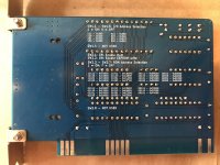
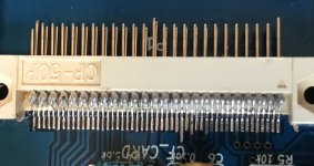
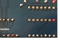
Also, post some good pics of the card that you assembled, showing your soldering on the back and on the cf slot.
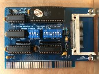
IMG_0404_small.jpgIMG_0405_small.jpgIMG_0403_crop.jpg

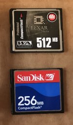
CF cards.jpg
Do you have a logic probe or oscilloscope ?
I do not have a logic probe. I do have an analog oscilloscope; I only know the very basics so far of how to use it.

No not reformat, Use something like DiskPart with the "Clean all" option or hddguru's low level format tool to completely zero out the whole cf card.
I'll try this next. https://hddguru.com/software/HDD-LLF-Low-Level-Format-Tool/
 
Looks like the two capacitors on the end farthest from the cf slot and also that top IC U5 each have a leg not soldered at all.

Maybe C2 at the bottom as well.
 
You really need to take a closer look at your soldering, Looking at the pic i can see a few joints that are in dire need of solder, Use a decent solder / Flux and IPA to clean the board before and after the touch up.
 
U3 pin 9 to U3 pin 20: No
U3 pin 11 to ISA edge connector pin A22: No
U3 pin 12 to U3 pin 20: No
U3 pin 19 to U4 pin 2: No
U5 pin 1 to ISA edge connector pin A27: No

Possibilities:
* Bad measurement
* Bad construction (e.g. solder joints)
* Bad PCB (i.e. defective manufacture)
 
View attachment 1239870

Just at a quick glance, I see these bad joints.. Also clean up all your flux with isopropyl and a toothbrush.
Thank you for pointing this out. After closer inspection, I found the following joints that I had left completely unsoldered.
  • C3 north leg (but leg and pad still passed continuity)
  • C4 north leg (still passed continuity)
  • U5 pin 1 (failed continuity)
I consider this a variant of Sattinger’s Law.

I scrubbed the back of the board with isopropyl alcohol and a toothbrush, rinsed with some water, then set it in front of a heater to dry for 10 minutes. Then I rechecked these continuities.

U3 pin 9 to U3 pin 20: No
U3 pin 11 to ISA edge connector pin A22: No
U3 pin 12 to U3 pin 20: No
U3 pin 19 to U4 pin 2: No
U5 pin 1 to ISA edge connector pin A27: Yes

I resoldered each of the joints above and rechecked continuity, paying attention to the display on the multimeter. No change for beeps, but here are the readings. I don't know the units.

U3 pin 9 to U3 pin 20: No (857)
U3 pin 11 to ISA edge connector pin A22: No (859)
U3 pin 12 to U3 pin 20: No (OL)
U3 pin 19 to U4 pin 2: No (827)
U5 pin 1 to ISA edge connector pin A27: Yes
 
Last edited:
I resoldered each of the joints above and rechecked continuity, paying attention to the display on the multimeter. No change for beeps, but here are the readings. I don't know the units.

U3 pin 9 to U3 pin 20: No (857)
U3 pin 11 to ISA edge connector pin A22: No (859)
U3 pin 12 to U3 pin 20: No (OL)
U3 pin 19 to U4 pin 2: No (827)
U5 pin 1 to ISA edge connector pin A27: Yes
Remove the IC's from U3 and U4 and check again, Placing your probes on top of the sockets, Taking care not to damage the sockets.

I gotta say, Continuity test's are not fool proof, Even if you get a beep from your meter it just means there is a path between 2 or more points, It doesn't mean it's a good path in this case.
 
Last edited:
Back
Top