• Please review our updated Terms and Rules here

Getting XT-CF-Lite/XT-IDE working

If we pick one of the failures of continuity:

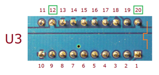
One failure is "U3 pin 12 to U3 pin 20: No (OL)"

Below is a photo of the solder side of U3 on my card. As can be seen, pins 12 and 20 are connected by a thick trace.
Expected is:
* On the solder side of the PCB, continuity between the solder blobs of pins 12 and 20.
* On the component side of the PCB, continuity between the socket contacts of pins 12 and 20.
1649059627979.png
 
U3 pin 9 to U3 pin 20: No (857)
U3 pin 11 to ISA edge connector pin A22: No (859)
U3 pin 12 to U3 pin 20: No (OL)
U3 pin 19 to U4 pin 2: No (827)
U5 pin 1 to ISA edge connector pin A27: Yes
I must have had the number order of U5 pins 11-20 reversed as I was doing this. I can remember it correctly by remembering that “U” is the shape of the numbering. New measurements:

U3 pin 9 to U3 pin 20: Yes
U3 pin 11 to ISA edge connector pin A22: Yes
U3 pin 12 to U3 pin 20: Yes
U3 pin 19 to U4 pin 2: Yes
U5 pin 1 to ISA edge connector pin A27: Yes

On the solder side of the PCB, continuity between the solder blobs of pins 12 and 20: Yes.

On the component side of the PCB, continuity between the socket contacts of pins 12 and 20: Yes.

Still no change in the response from the computer:

“Master at 300h: not found
Booting C>>C
Error 80h!
Booting A>>A”
And then the A-drive never stops accessing.
 
* The XUB in your EEPROM is configured for a base I/O address of 300h. Earlier, you did some tests of the base I/O address switches on the XT-CF-Lite card. Have you confirmed that those switches are back at the 300h setting ?

1649125982759.png

* Do you now see the LED on the XT-CF-Lite card light momentarily when the XUB tries to interrogate the CF card for model information ?

* Time again to try different CF cards.
 
* The XUB in your EEPROM is configured for a base I/O address of 300h. Earlier, you did some tests of the base I/O address switches on the XT-CF-Lite card. Have you confirmed that those switches are back at the 300h setting ?
* Do you now see the LED on the XT-CF-Lite card light momentarily when the XUB tries to interrogate the CF card for model information ?
* Time again to try different CF cards.

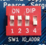
SW1 is set to 1110.

The LED on the XT-CF-Lite card has never lit, ever. Not even one single blink.

The two CF cards I have been using are the two I showed in my photograph above. In post #62 I was using the 256 MB. card which I recently reset using HDDGURU's program, as told earlier. I tried the 512 MB. card and no change.
 
The LED on the XT-CF-Lite card has never lit, ever. Not even one single blink.
Are you sure that switch 1 is actually working ?, The LED is fitted correctly ?, The soldering of the CF socket is good ?
 
We now know that you have an oscilloscope. I think that it's time to use it. With the base I/O switches set to 300h, use the procedure at [here] to test the I/O decode circuitry.

( Of course, in your present situation, to boot from a floppy, you will need to disable the EEPROM. )
 
Booting A>>A”
And then the A-drive never stops accessing.

Does this hang forever happen if you don't have the CF card plugged in, or does it make no difference? (Maybe this test was already done?)

I'm saying this based on a quick glance at the schematics, I could be wrong, but it looks to me like it would be physically *possible* for this card to stomp on the I/O ports used by the PC floppy controller if the wiring for the I/O 74LS688 and the DIP switches were screwed up in such a way that the card became active in the 3E0h window. If that were happening then it seems in theory at least the CF card might be loading the bus when you try to boot from a floppy, and that's why it just wanders off and dies. (And this would also explain why it never detects the drive at 300h.)

This card doesn't have a buffer between the bus and the CF card, so if the CF card is yanked out it should be impossible for any theoretical interference with the disk controller (or any other I/O port) to happen. If it still wedges and dies trying to boot from drive A with no card in place you have a bigger problem.
 
His A: drive booting problem disappears if the 'ROM enable' switch on the card is set to disabled.

Is it normal for the XTIDE BIOS to not correctly be able to boot from the A-drive if a card isn't detected? Does this happen on both of the OP's machines?

(Since it seems like the EPROM otherwise works, IE, it's initializing and from the banner it looks like it's correctly ID-ing its place in memory I guess I don't understand how it could be blowing up booting from a floppy unless there's a bug in the version of the XTIDE code it's flashed with *or* the I/O part of the card were interfering. And since there's no buffer, the IOR/IOW signals and the data lines terminate directly on the CF card plug, it would seem like pulling the CF card would resolve any possible I/O conflict.)
 
Last edited:
Is it normal for the XTIDE BIOS to not correctly be able to boot from the A-drive if a card isn't detected?
No

If the XUB can not successfully put the CF card in 8-bit mode it will not issue the " Drive identify " command and should then go on to boot from floppy.
 
Is it normal for the XTIDE BIOS to not correctly be able to boot from the A-drive if a card isn't detected?
No

If the XUB can not successfully put the CF card in 8-bit mode it will not issue the " Drive identify " command and should then go on to boot from floppy.
Which I have substantiated by:

I have the same XT-CF-Lite card as the OP, and it is at the same XUB version, the latest release, release R622.
If I remove the CF card from my XT-CF-Lite, then power up, it does boot from disk in A:, in both of the following situations:
* When the XUB's hotkeybar appears, I press the A key to request a boot from A:.
* When the XUB's hotkeybar appears, I press nothing. The XUB tries C: and when that is unsuccessful, tries A:

But maybe if I had the OP's setup (Compaq Portable 1, same motherboard BIOS, same cards, etc.), I might see different.

I have noted something that may be a red herring (or even possibly, a dead herring). Above, when the XUB on my XT-CF-Lite attempted to boot from the non-existent CF card, the error code shown on-screen was always 1h (invalid value passed or unsupported function).
In post #62, the error code the OP gets is 80h, the error code that I expected to see.

Does this happen on both of the OP's machines?
No. At post #36, the OP wrote, "I tried the XTIDE card in the Epson Apex 1 again. It did a "master, slave" search and found neither, gave error 1h, and booted from the floppy drive."

( Interesting: the unexpected 1h again ! )
 
I have noted something that may be a red herring (or even possibly, a dead herring). Above, when the XUB on my XT-CF-Lite attempted to boot from the non-existent CF card, the error code shown on-screen was always 1h (invalid value passed or unsupported function).

Huh. I was going to hazard a guess that the reason this card spits out the wrong(?) error message when there's no card present is the Sergey XT-CF design takes a shortcut that prevents it from returning a predictable response in that situation. (That resistor R5 that the instructions tell you to omit is a pull-down on D7 which is there to provide a clue that the plug is unpopulated. The reason it's omitted is because with no buffer in front of it to clearly load the bus with 7 floating inputs and the one tied down one that resistor would be fighting against the pull-ups that are typically terminating the data bus on the motherboard, and probably losing.) But out of curiosity I tried pulling the IDE-SD adapter I use in my homemade card that does have the buffer and resistor implemented and it also returned a 1h. So... bug? (I'm running about a year-old version of the firmware, not the latest.)
 
In regard to nil CF model information presented on-screen, it will be interesting to hear the results of the oscilloscope measurements pointed to in post #67.
 
My next question is when you checked continuity for the cf card, were you using the pins on the male side of the connector? or the points where it attaches to the board. If you used the board points, pressing on them to measure could complete the circuit, but it might still be broken when not pressed on.
 
My next question is when you checked continuity for the cf card, were you using the pins on the male side of the connector? or the points where it attaches to the board. If you used the board points, pressing on them to measure could complete the circuit, but it might still be broken when not pressed on.
When I checked continuity on the CF card pins, I put the probe on the card end of the pins, not the circuit board end.

We now know that you have an oscilloscope. I think that it's time to use it. With the base I/O switches set to 300h, use the procedure at [here] to test the I/O decode circuitry.

( Of course, in your present situation, to boot from a floppy, you will need to disable the EEPROM. )

Here are the steps I followed. Base I/O SW1 set to 1110 = 300h. CF card slot was populated.

1. Remove XTIDE board. Hook the positive oscilloscope probe to U3 pin 19. Reinstall XTIDE board.
2. Hook the negative oscilloscope probe to the metal computer chassis.
3. Turn off SW 2.1 to disable the XTIDE board.
4. Boot from floppy.
5. Turn SW 2.1 on.
6. Ran DEBUG and executed the line commands as told.
- A 100
xxxx:0100 MOV AL,0
xxxx:0102 MOV DX,300
xxxx:0105 OUT DX,AL
xxxx:0106 MOV DX,310
xxxx:0109 OUT DX,AL
xxxx:010A JMP 102
xxxx:010C <----- at this line just press the [ENTER] key - this will return DEBUG's dash prompt
- g=100

7. Turn on the oscilloscope and make various adjustments on the view.

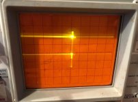
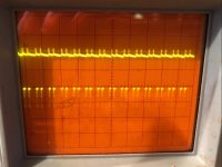
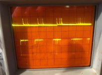
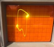
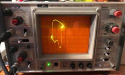
I can't tell if there is a pulse or not. When I disconnected the negative probe, there was a true flatline. Here are some photographs with both probes attached. In the last 2 pictures, the image was "still" (even though I know it's technically a moving line). Because I know analog oscilloscopes are highly susceptible to screen burn, for the last 2 pictures I only held the image on the screen long enough to take each picture.
Screenshot 2022-04-06 205806.jpgScreenshot 2022-04-06 210750.jpgScreenshot 2022-04-06 210803.jpgScreenshot 2022-04-06 210824.jpgScreenshot 2022-04-06 210849.jpg
Naturally, I can give the x-scale, y-scale, and time scale if desired. I would have to reread it, though.
 
When I disconnected the negative probe, there was a true flatline.
So you are using the ground point on the second probe to provide the ground reference to the oscilloscope.

You would get a 'cleaner' looking signal if you only used one probe, the probe's tip for the signal, and the probe's ground point to provide the ground reference to the oscilloscope. If I'm measuring a pin on a chip, I would hook the ground point of that probe to the ground pin of the chip. However, for what you are doing, which is, "Is there a changing TTL signal there are all?", what you are doing is good enough.

Here are some photographs with both probes attached.
Five photos, one for each of the five steps:

1. Expect to observe pulses on pin 19 of the U3 chip. <--- No point in proceeding if these pulses are not present
2. Expect to observe pulses on pin 3 of the U4 chip.
3. Expect to observe pulses on pin 6 of the U4 chip.
4. Expect to observe pulses on pin 7 of the CF connector.
5. Expect to observe pulses on pin 32 of the CF connector.


Photos 2 and 3 (for steps 2 and 3) is what we expect to see. I can see pulses there. You would get a better viewing result by suitably adjusting the time-base and trigger.

Photo 1 is unclear, but appears to be showing a changing state signal. If you change one of the base I/O switches on the card (i.e. card no longer at 300h), pin 19 would then always stay HIGH.

In the last 2 pictures, the image was "still" (even though I know it's technically a moving line). Because I know analog oscilloscopes are highly susceptible to screen burn, for the last 2 pictures I only held the image on the screen long enough to take each picture.
Those photos will be the ones that correspond to steps 4 and 5, where you are measuring pins on the CF connector.

I really don't know what those photos show, but what you see on the oscilloscope for steps 4 and 5 should be identical to what you see at steps 2 and 3 - because you are measuring the same thing:
* Pin 3 of the U4 chip (step 2) connects to pin 7 of the CF connector (step 4).
* Pin 6 of the U4 chip (step 3) connects to pin 32 of the CF connector (step 5).

Is that what you see ?
 
However, for what you are doing, which is, "Is there a changing TTL signal there are all?", what you are doing is good enough.

It's for issues like this I'm happy I happen to have a good old fashioned logic probe in my toolbox. (A scope will certainly work but a logic probe has the advantage of simplicity. Point and shoot, er, beep.)
 
Five photos, one for each of the five steps
No, you misunderstand. All 5 photos are of U3 pin 19. I only varied the time scale and maybe x-scale and y-scale. Before looking at any of the other pins, like you said, I wanted to see if there was a pulse at all at U3 pin 19. Is there a pulse?
 
Back
Top