• Please review our updated Terms and Rules here

Osborne 1 New mechanical keyboard

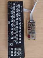
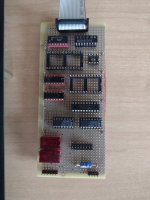
I did some mental pin count to signal name reconciliation in my head for the 20 pin connector on the circuit board, and I realized there is an unused pin. So I used it....

1696210999073.png

Once I get it built, then I can see which keys generate which codes in the 1188 so I can figure out the programming for the 2Kx8 NVRAM.
 
Well, without the keyboard kit, I would probably not have gone down this path. Pure, and complete & working, Parallel ASCII keyboards, are very scarce. And, do this, I have complete control over the ASCII codes it will produce. Add to that, the 'function keys' I can come up with using the Ctrl-Shift combo. This is gonna be great.
 
All of the key switches are in, and the mods made to the keyboard, and I just finished mapping out the key matrix..... Next up is order the parts to make the encoder circuit to get ASCII codes out....
 

Attachments

  • KeyboardSchematicSh1.pdf
    13.4 KB · Views: 3
I'm going to use that modified keyboard on my 'WOPRjr' S-100 machine I'm slowly building.... :) I bought some 14 segment displays to spell out 'WOPR'. I'm going to have it cycle the letters from off to on using a PWM LED dimmer, a 555 timer, digital pot, controlled by a divided down system clock.....
 
I working out the keyboard interface to make is ASCII Parallel, I was thinking that I had to figure out an approach for auto-repeat. Well, in doing more work on the schematic identifying components, pins, etc. I happened to come across this in the datasheet for the encoder: "If a key is held longer than the autorepeat delay of 660 mS, the cycle is repeated again at a rate of 5 times per second.". Well then, problem solved! I'm sure a CPU running at 4MHz can keep up with that.
 
After I get the decode board built for mine, and I know things are working as planned, I need to get a case and key-caps. Case is easy, I'm going to use a Hammond 1456KE3WHBU case. Key caps are going to be a bit more difficult given the layout.
 
While I try my hardest to learn and do things on my own, there is one thing I sure could use someone else to help me out with. Since I do not have an Osborne that my keyboard is going into, but rather building a one of a kind case from scratch, if anyone either has a dimensioned drawing of the keyboard cover cutout, or could measure the one they have, that would be an awesome help. I grabbed a pic online and started to come up with a drawing, but I don't have any dimensions. I'm hoping to make it as accurate and as nice as possible.
 

Attachments

  • KeyboardCutout.pdf
    5.7 KB · Views: 1
Well, I have the keyboard encoder board started. The sockets and some chips are in and the power & grounds are wired.....
 

Attachments

  • Keyboard1.jpg
    Keyboard1.jpg
    1.8 MB · Views: 7
  • Keyboard2.jpg
    Keyboard2.jpg
    1.8 MB · Views: 7
I'll do that this evening.
Thank you, thank you, thank you. I will probably get the encoder board wired this week. I already have the code I'm going to put in the NVRAM chip. With the two character hex display, I can test it without need any computer.
 
Well, I have it working. At least the circuitry works. I do need to make some tweaks to the config of the NVRAM, but that should be easy enough once I sit and go through all of the keys. But I'm pretty pleased with it so far. Anyway, here is the schematic in case anyone is interested.
 

Attachments

  • Keyboard-V1.pdf
    23.4 KB · Views: 6
Well, after some tweaks to the character generation code, it is putting out the ASCII values just like I want. I got to thinking, the NVRAM could also be loaded with EBCDIC, or anything for that matter. So that is an added bonus. All I need now if a metal case to cutout to mount it, and the appropriate key caps......
 
I'm in the process of building this kit for an OCC1A. The one part I'm not clear on is installing the 3/4 Amp Poly Switch Re-settable Fuse on pin 19 in the computer itself. Does anyone have some clear images of this installed?
 
I'm in the process of building this kit for an OCC1A. The one part I'm not clear on is installing the 3/4 Amp Poly Switch Re-settable Fuse on pin 19 in the computer itself. Does anyone have some clear images of this installed?
You just need to solder it across the 2 jumper pads. It is just like using a bodge wire between 2 pads.
 
Can someone with a working kc4bqk O1 keyboard tell me the value of R4? It was missing from my kit and the caps lock toggle is not working.
 
Back
Top