• Please review our updated Terms and Rules here

Using a C1084 with Sinclair or Amstrad

DarthKur

Experienced Member
Joined
Jan 2, 2007
Messages
171
Location
Western North Carolina
I have both a Sinclair Spectrum +2 and a Amstrad CPC 464. Now, since I reside on this side of the pond I never get to see the true colors displayed for either computer. If I understand correctly the RGB signal is independent of either NTSC or PAL. So if I could hook each one of these up to a Commodore 1084 RGB monitor then I should be able to get an accurate screen image. If that is indeed the case then all I would need are the appropriate cables to link cpu and monitor together for each. Are such cables available? Were the Commodore monitors popular over in Europe? The only thing I can seem to find are scart cables. This would also be helpful if I ever happen to be able to get my hands on a BBC B.
Of coarse if I'm wrong about the signal compatibility then I guess everything else is moot.
 
If that is indeed the case then all I would need are the appropriate cables to link cpu and monitor together for each. Are such cables available?

I am also interested to the answer to this question. I own a BBC(b) and at the moment I just run it through the RF modulator. It would be good to know if such cables exist and what the connectors plug into.

Tez

P.S. it looks like I might soon own a Amstrad CPC 464 also. This comes with it's own monitor.
 
The Commodore 1084 monitors came in a wide varity of models. Some have two different DIN connectors for analog and digital RGB, some have one DB9 connector and a switch, some actually have SCART + one of the DIN connectors. So look at the back side of your monitor which actual inputs it has, and it gets easier to tell if you will be able to obtain a cable. If you like to solder, everything is possible.

I'm not sure but I believe at least the ZX Spectrum +2 has a TTL RGB signal, just like e.g. the BBC Micro has. It means that either you run it to the digital RGB input on your monitor, or make a cable with some voltage dividers; resistors are the easiest approach but not neccessarily the best. I have once made a cable for my BBC Micro to connect to a 1084S, the one with a DB9 input. However digital RGB didn't work on that monitor so I had to convert the signal to analog 0.7 - 1V levels.

Whether or not a RGB signal is affected by video modes, I'm unsure but at least I believe it has a sync rate 50 or 60 Hz that will make a difference. Fortunately most 108X monitors can handle both irregarding which country they were manufactured for.

Once of those days I'll make a BBC to SCART cable too. I already have all the parts, I only need to find time to get going. It isn't cruicial as I already have a working solution but it would be slightly more practical for me if I bring along the computer.
 
My 1084 monitors only have the DB9 with the switch. And unless I had someone sitting right beside me and showing step by step how to go about making a cable I'd be lost. I sure wish mine had a scart connection. There would be no problem at all then since I have scart cables for both right now. Of coarse none of my monitors or TV's have scart inputs so I have to use an adapter to transfer them to RCA/AV leads.
As for a BBC B to scart cable, there's a guy on Ebay selling them but his store, the-sinclair-shop, is on a "vacation hold". I never encountered that before. It makes all of the persons goods unavailable, even just to look at.
Carlsson, any way to coerce you to make these? :D
As for the BBC B, does anyone happen to have one they'd be willing to part with? :mrgreen: Preferably with a compatible floppy drive too. Not to detract terribly much further from the original topic but would a data recorder/tape deck from the states work find with a beeb, or any other European pc or would I also have to have a specific one for it? I'd love to have an original of coarse. Just have to remember every heavy item makes the shipping skyrocket a bit further.
 
Last edited:
I must disappoint you that I hate to solder cables, but sometimes do for neccessity's sake. A circuit board - fine, no doubts but cables don't hold still in the same way.
 
C=1084D: http://pinouts.ru/Video/C1084dd_pinout.shtml
ZX Spectrum +2/+3: http://www.hardwarebook.info/ZX_Spectrum_Plus3_VDU
Amstrad CPC: http://www.hardwarebook.info/Amstrad_CPC_Monitor

Just as a warning, it seems the ZX Spectrum 128 differs from the +2/+3:
http://pinouts.ru/Video/ZxSpectrum128Rgb_pinout.shtml

In the same way, the CPCplus 6128 has a different pinout than the older CPC:
http://www.hardwarebook.info/Amstrad_CPCplus_Monitor

The BBC Micro is harder to find graphical pinouts for, but this should be correct:
Code:
   \/        \/ = notch
*0    *R     R  = red    (pin 1)
   *5        G  = green  (pin 2)
*S    *G     B  = blue   (pin 3)
   *B        S  = sync   (pin 4)
             0  = 0V     (pin 5)
             5  = +5V    (pin 6)

I'm unsure at what signal level the CPC operates - I think it uses analog 1Vpp signals. The ZX clearly uses 1.7Vpp which may be too strong for analog RGB and too weak for TTL. The BBC reaches about 3.3V IIRC.

I noticed that for the Spectrum pinouts it lists specifically the +2a/3 and not the original +2. Is it safe to assume the they are of the same configuration?

Yes, you are correct about the CPC video signal. The info I found stated "video signals are PAL frequency 1v p-p analogue RGB with composite sync".


9 pins? Gimme the parts and the pinout and I'll volunteer (for one).--T
Thanks. I'll send you a PM.


Would any given DB9 cable work for this project? The same with either a 6 DIN (CPC) or 8 DIN (Speccy)? Or would it have to be the actual Commodore/Amiga and Sinclair/Amstrad cables?
 
Err.. you're (Terry rather) is about to manufacture a cable. The signals don't care from where the cable parts come, if you take a 6-pin DIN cable and cut off one connector or solder everything from scratch. However if you had a 1084 monitor with a 6-pin DIN connector, you can't expect to connect any 6-pin video cable to it since you already have seen two drastically different pinouts using the same connector.

Good question on the Spectrum +2, +2A and +3 since we already observed a difference in the forerunner Spectrum 128. I'm not sure, perhaps it is a matter to research on the Internet and/or printed documentation.
 
Ok, I've offered to put something together, but I'm thinking straight-thru wiring. If the voltage needs to be changed with a resistor or whatever, I'll need that info too. I'm not smart enough to figger it out myself. I'm just an ol' dumb mechanic who happens to be good with my hands, so simple (minded?) soldering is no problem. (Actually, I find it rather therapeutic)

--T
 
The idea behind using resistors as voltage dividers depends on the fact that the monitor - the 1084 in this case - has its own impedance at 75 Ohm. By soldering a resistor to each wire from the computer, you will create the divider circuit. I'm not good in electronics neither, this is just the way I understand it. Someone more skilled could correct me. It should be possible to implement with diodes too, but for most people and monitors it works just fine with resistors in case the signal is too strong.

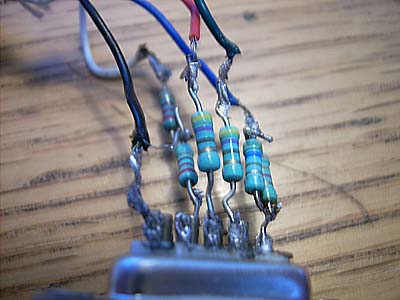
Here is a picture of my home made BBC cable:
bbc-kabel.jpg


The only reason why I have two resistors connected in series and two resistors connected in parallel is that I was short of suitable resistors and had to improvise. In my case, abut 470 Ohm was enough. Other cable designs suggest anything from 220 Ohm and upwards, but probably values well below 1 KOhm. If the ZX Spectrum outputs a signal about 1.67V, perhaps 100 Ohm is enough for the voltage dividers. There are web pages about this, possibly even with calculators.
 
Back
Top