• Please review our updated Terms and Rules here

House wiring...

kishy

Veteran Member
Joined
Aug 22, 2009
Messages
1,065
Location
Windsor, ON Canada
I have an irritating, probably easy to fix problem with two "previous homeowner installed" light fixtures in a closet that merges with the crawlspace. This closet/crawlspace is where my computer stuff lives so this problem will come back to bite me if not corrected soon (I need to be able to see in there).

The symptom: the two 60W incandescent lightbulbs do not fully light up. The one closer to the supply line is roughly half as bright as it should be and the next bulb is about half as bright as the first. CFL's flicker and don't give off any useful light. If two non-matching incandescent bulbs are used inconsistent results can happen (which bulb is brighter will switch back and forth).

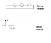
The problem: the two bulbs are wired in series.

attachment.php


I know what needs to be done to fix this...put the bulbs in parallel and then the [(set of two bulbs in parallel) in series with the switch]

However, one bulb and the switch just so happen to be encased in a finished wall. If I had to venture a guess I'd say the exposed lightbulb socket was probably placed in a pre-existing junction box (and just had the lid removed to put the light in it) and the circuit was fine before that was done. That's just a guess though.

The easy solution would be to take out the light socket in the finished wall and just jump the wires together, but it's nice having light in that particular spot (however if I had to pick only one, I would sacrifice this one).

Although I really don't think it's possible, does anyone see a way I can do this without ripping up the wall and without removing the second lightbulb socket?

Also while I'm at it, which wire is supposed to be switched...white or black?
 

Attachments

  • lighting.JPG
    lighting.JPG
    10 KB · Views: 1
There is not really enough information here to answer the question. Is the hot (from the power panel) wired to the switch or one of the lights? What color wires are wired to the swtch and each lamp? How many white/black pairs are in each box? Do you have a meter?

Kipp
 
There is not really enough information here to answer the question. Is the hot (from the power panel) wired to the switch or one of the lights? What color wires are wired to the swtch and each lamp? How many white/black pairs are in each box? Do you have a meter?

Kipp

Not sure which wires go where yet.

Do have a digital multimeter as well as a Square D "wiggy". I trust the multimeter more but know the wiggy is probably the better tool.

Please advise of what to do to discover the info you need. I do not trust that the wire colours are enough to go by, this was done by someone who clearly didn't understand circuitry.

Also note that physically tracing the circuit through the house is impossible, it's piggybacked off another circuit in another room which could go anywhere from there.
 
Well it's tough to tell you exactly what to do then. If the hot wire (black) goes to the switch, then the first lamp should be tied to the switch on one side and the white wire on the other. The switch should have the same color wire on both terminals. The second lamp should be tied to the first black on one terminal, white on the other.

My suggestion would be to turn off the power to this circuit. Pull the switch and both lamp fixtures but do not disconnect them. Write down what color wires are in each box. Then I'd turn the power back on and with the switch off, check for voltage between each terminal of the switch and ground. If you find it then the hot is connected there.

Kipp
 
Open the wall and get an electrician if you can't clearly see what is going on. A new sheet of wallboard material is far cheaper than any mistake you might make. And even if this forum were full of qualified electricians, none would be safe to give you a remote diagnosis on something they can't see.
 
Well it's tough to tell you exactly what to do then. If the hot wire (black) goes to the switch, then the first lamp should be tied to the switch on one side and the white wire on the other. The switch should have the same color wire on both terminals. The second lamp should be tied to the first black on one terminal, white on the other.

My suggestion would be to turn off the power to this circuit. Pull the switch and both lamp fixtures but do not disconnect them. Write down what color wires are in each box. Then I'd turn the power back on and with the switch off, check for voltage between each terminal of the switch and ground. If you find it then the hot is connected there.

Kipp

Surprise surprise, the wires going to the switch are white and black and there is no ground wire going to the box or switch (meaning that the box itself isn't grounded, so testing is useless)

Edit: there IS a ground wire, it's hidden very well. I'm going to investigate if that ground wire actually is grounded though by checking continuity of it to a grounded spot on the circuit this one branches off of (which had to be turned off to get the closet lighting off)

Edit again: ground was not grounded to ground. At the point where the wires go behind the finished wall there is a connection of wire nuts for white black and ground. The ground wires had slipped out of their wire nut (it wasn't big enough). I put a larger one on then checked it and it's grounded properly now. Testing will commence soon since it can't really do any harm to poke at the wires with insulated test prods.

Open the wall and get an electrician if you can't clearly see what is going on..

That's looking like a good idea. I'll continue to visually inspect and if something jumps out at me (in the good way) I'll investigate it but of course very carefully.
 
Last edited:
I never use wire nuts on the ground wire--and I'm not even certain if using them conforms to code in some areas. I twist the wires for perhaps an inch and a half along their length, then apply a crimp sleeve (looks vaguely like a .22 cal. shell casing). If there's a fixture, receptacle or switch in the box (i.e. it's not simply a junction box), I leave one ground lead long for attachment to the fixture.

21XADT8P9ZL._SS500_.jpg


Ground leads can mean the difference between life and death--it's worth doing them right. Also, it's worth twisting wires together used in wire nuts before the nut is applied. I've seen too many wire-nutted connections where a wire can simply be pulled out--that's a fire hazard.
 
Last edited:
I never use wire nuts on the ground wire--and I'm not even certain if using them conforms to code in some areas.

Wire nuts are used because it's a point where two lengths of wiring are being joined, not because a junction box is present. That in itself is probably a big problem, but if they're not connected with a wire nut then they simply are not connected.

Ground leads can mean the difference between life and death--it's worth doing them right.

I absolutely agree...which is why I did it wrong lol. Either it's done wrong or it's not done, I don't have an option here...blame the previous homeowners. I'd rather have a noncompliant but functional ground than none at all.
 
Wire nuts are used because it's a point where two lengths of wiring are being joined, not because a junction box is present. That in itself is probably a big problem, but if they're not connected with a wire nut then they simply are not connected.

Do you mean to tell me that your wires are joined outside of a box? Wow--a "homeowner's special".

A loose wire nut where the conductors are not brought firmly into contact with one another is a resistive contact--and a fire danger.

Remember the aluminum house wiring of the 1950s? It was a fire danger not because of the wire itself, but because it was almost impossible to make solid contact with conventional fixtures. Refitting by crimping (using a special tool) copper pigtails to the aluminum leads fixed that problem.

You'll cringe when I say "don't you mean the aluminum house wiring of the 1970s which this house has?"

The wires are joined where they are, by the way, because whoever did it ran out of one kind of wire then ran out for some of the other kind (dumb). The fixtures and switch are in boxes but that joint happened halfway between two boxes.

There's an electrician in the family, he'll be checking it out for us in the near future. I'm not messing with it anymore, there's no use. The wires to and from one light are aluminum, then the wire nut joint, then copper to the other light and the switch. Fortunately it's the only place in the house that's been messed up this badly.
 
I wouldn't bet on it.

Pull the cover off the breaker box. If you see aluminum then plan on replacing what needs to be replaced to make it safe. If your family electrician is a licensed electrician then he/she will know what to do.

11 1/2 years ago we were looking around to buy a house. Every house in the area was built in the early 70s and every one I walked into I pulled the panel cover off of.

We walked away from some beautiful older homes because of aluminum wiring. I remember all the trailer fires back in the 70s and 80s that were caused by that.

All the wiring into and out of the breaker box is aluminum.

The home inspector we hired had warned us about the issues that do exist with aluminum wiring so it's not really surprising to find someone opposed to it. Googling finds some frightening examples, that's for sure.

It would appear that the significant problems happen in overloaded or just heavily-and-constantly loaded circuits, not those which are only being used lightly and infrequently...yes?

Sometimes ignorance is bliss. I might actually lose sleep over this.
 
You're right--it was the mid 60's to early 70's that used aluminum wiring. Somehow, my mind couldn't wrap itself around a notion being that stupid that late in time.

More info on aluminum house wiring

The web site explains the process pretty well. You should check to see that all of your fixtures (switches, outlets, etc.) are of the aluminum-rated type. Often, a homeowner will "upgrade" to get a new look and use ordinary copper-rated fixtures and that can lead to big problems. The best solution, short of replacing all of the wiring is to employ the copper pigtail crimp connector. The connectors themselves aren't too expensive, but the tool is very expensive.

First it was aluminum wiring, then polybutylene plumbing.

Makes for full employment, I suppose.
 
Last edited:
You're right--it was the mid 60's to early 70's that used aluminum wiring. Somehow, my mind couldn't wrap itself around a notion being that stupid that late in time.

More info on aluminum house wiring

The web site explains the process pretty well. You should check to see that all of your fixtures (switches, outlets, etc.) are of the aluminum-rated type. Often, a homeowner will "upgrade" to get a new look and use ordinary copper-rated fixtures and that can lead to big problems. The best solution, short of replacing all of the wiring is to employ the copper pigtail crimp connector. The connectors themselves aren't too expensive, but the tool is very expensive.

First it was aluminum wiring, then polybutylene plumbing.

Makes for full employment, I suppose.

That's the site I've been looking at, slowly sinking lower in my chair and looking around fearfully expecting a cloud of smoke at every outlet (and there are quite a few in this room that was finished after the house was built, presumably by "a" homeowner)

Priorities would be to inspect dryer, stove and air conditioner hookups I suppose.
 
Priorities would be to inspect dryer, stove and air conditioner hookups I suppose.

Actually, you're probably safe there--aluminum for high-current feeds such as dryer, furnace and oven has been used for a long time (still may be used--I haven't checked NEC to see if it's still allowed) and the fixtures are designed for it. You may well have the main drop from the distribution transformer as aluminum all the way to the distribution panel.

Where I'd start looking is at the bathroom and kitchen outlets, where high-draw appliances are likely to be used. While you're at it, if you don't have one in-circuit there, consider installing a GFCI or two.

What with plasma TVs and all, your family/living/media room may be another place to look.

Take heart--after 20 years, I still find "homeowner's special" problems here--I suspect that the garage lighting cirucuit has the neutral and hot sides reversed (too many 4-way switches probably got someone confused), but they're all ceiling fixtures, so I'll find the problem when I get round tuit.

I'm fortunate to be on a rural co-op here--all outside wiring is buried, with a 6600V feed coming up my driveway to the transformer in my front yard. All copper--the direct-bury HV feed looks like garden hose and weighs a couple of pounds per foot.

We only have CRT TVs in the house. I was really surprised when I read that they can be more efficient than LCDs (seems like a step backwards). Since we're fairly energy conscious we almost never leave any on without being present.

Almost all lights except the ones in this closet/crawlspace have been replaced with CFLs. Trying to narrow it down to areas where a lot of electricity is used, the fridge would probably count as one as would the chest freezer about 10 feet in front of my desk. Microwave perhaps? Giving it some thought, I think the freezer and computer are on the same breaker.

I'm on my laptop 9 times out of 10 but my desktop does get used (not frequently enough to be a concern I'm sure, and I never leave it on when not in use)

There's one outlet in the upstairs bathroom and it is a GFCI. The downstairs bathroom is combined with the laundry room and has one outlet...not a GFCI, and is in fact the outlet that the crawlspace mess branches off from. The washing machine is on that outlet. That's the outlet I charge my drill batteries on but it's not like I'm charging them 24/7/365.

I guess my big question would be this: do the copper wire connections create a problem under any load, or is it only with low loads, or is it only with high loads?

Also it would appear the problem relates to an insulating film forming on the aluminum...would a light sandpaper treatment on wire ends and then firmly tightening screws be at all helpful? I have no intentions to "fix what isn't broken" at this point but it'd be nice to know what's possibly coming down the pipe.

"Homeowner's special" - I like this term. Reminds me of the "$5 ebay special" USB hubs I got that retain electricity after being unplugged.
 
Last edited:
Since I'm not there to see your setup, I'm going to beg off of offering an opinion. Sounds like it's time for your electrician-relative to have a peek at your place.
 
Simply having two light bulbs in series instead of parallel shouldn't make any difference.

Instead, I suspect this is the problem:

Also note that physically tracing the circuit through the house is impossible, it's piggybacked off another circuit in another room which could go anywhere from there.

We had the same deal here with lights running very dim. All sorts of goofy problems - the only solution was to tear it out and rewire a new circuit from scratch.

Regarding the aluminum wiring, I wouldn't touch the stuff, nor a house with it installed. Just too many ways for it to go bad, especially with any past non-compliant wiring activities going on.

Heck though, half of our house still runs on knob-and-tube. :mrgreen: (Which isn't necessarily unsafe, as long as it's in good condition.)

Our home was built pre-1900, divided into apartments, and re-joined into a single-family house. New circuits were simply tapped into the knob-and-tube; some circuits seemed to run in circles; some things were tapped into the + of one circuit and the - of another; with the main shutoff tripped, half of the house stayed live... I could go on for some time with this list.

The solution, a brand new meter and breaker box ($3,000). Now as I restore each room (paster, woodwork, plumbing, etc.), I remove as much old wiring as possible and run a brand new circuit to the new service panel. I leave the ceramic fittings for historic interest, but pull out the wiring so it doesn't look 'scary'.
 
Simply having two light bulbs in series instead of parallel shouldn't make any difference.

Instead, I suspect this is the problem:


We had the same deal here with lights running very dim. All sorts of goofy problems - the only solution was to tear it out and rewire a new circuit from scratch.

Regarding the aluminum wiring, I wouldn't touch the stuff, nor a house with it installed. Just too many ways for it to go bad, especially with any past non-compliant wiring activities going on.

Heck though, half of our house still runs on knob-and-tube. :mrgreen: (Which isn't necessarily unsafe, as long as it's in good condition.)

Our home was built pre-1900, divided into apartments, and re-joined into a single-family house. New circuits were simply tapped into the knob-and-tube; some circuits seemed to run in circles; some things were tapped into the + of one circuit and the - of another; with the main shutoff tripped, half of the house stayed live... I could go on for some time with this list.

The solution, a brand new meter and breaker box ($3,000). Now as I restore each room (paster, woodwork, plumbing, etc.), I remove as much old wiring as possible and run a brand new circuit to the new service panel. I leave the ceramic fittings for historic interest, but pull out the wiring so it doesn't look 'scary'.

How wouldn't it make a difference? Placing them in series reduces the voltage, in this case to what...about 55-60V per bulb? At least that's the case for DC circuits, I'm not sure if AC electricity has any little weirdnesses that prevent that law applying to it.

We'll have to sell the house if it comes to a point of rewiring the whole thing. We cannot and never will be able to afford, nor could we ever pay off if financed, that kind of expense.

Interesting to see though how, while code compliance is definitely a nice helpful thing, somehow people always find a way to weasel past it with reasonable success.
 
How wouldn't it make a difference?
Because light bulbs use a very small amount of electricity. If the circuit can't provide enough power for two lousy light bulbs, you've got something seriously wrong.

We'll have to sell the house if it comes to a point of rewiring the whole thing. We cannot and never will be able to afford, nor could we ever pay off if financed, that kind of expense.
It would certainly be overwhelmingly expensive to do all at once, in addition to rendering the home unusable for an extended period of time. That's why we coughed up the money for new service panel, so I can wire the rest as we go.

If you were to install a new circuit now, say for a new entertainment / computer room, you'd have nothing to connect to other than the existing problematic service box...

Interesting to see though how, while code compliance is definitely a nice helpful thing, somehow people always find a way to weasel past it with reasonable success.
I don't mind doing most of the romex circuit wiring myself - lights, outlets, switches. That stuff is very time consuming but not difficult, and easily accomplished with standard parts from Home Depot (unless you have aluminum wiring, that is). But for big stuff - connecting a new service panel to the pole, for instance - I'm more than happy to have someone else do it. :cool:
 
Back
Top