• Please review our updated Terms and Rules here

Wiring Schematic Questions

fred3rd

Experienced Member
Joined
Apr 29, 2006
Messages
213
Location
Central Pennsylvania U.S.A.
I know this is totally off topic but here goes. I'm building a wind turbine, small scale. I'm working on my charge controller and control panel. I posted the folowing question in a forum called Turbine Zone. I got a deer in the headlights stare. So I figures I'd ask my friends here who are more electronic savvy. Here's the question...

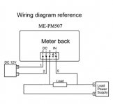
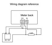
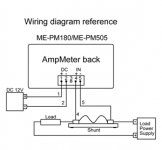
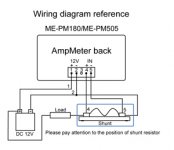
The last two ingredients for my turbine control panel/box arrived today. An Amp meter and a Volt meter. Both digital led display. Below are the wiring diagrams that came with them. I want to hook them both up to my charge controller at the turbine input point to monitor my turbine output. The two things that are confusing me in these diagrams is the load and load power supply. Do I need to hook up a light bulb to create a load? Is the turbine the load power supply? It would be a great help if someone could clarify this for me.
amp1.jpgamp2.jpgvolt1.jpgvolt2.jpgvolt meter.jpg
 
Do you want to monitor the charge to the batteries from the turbine, or the draw on the batteries from whatever you're powering (e.g. an inverter)?
 
I want to monitor the output of the turbine which will vary with the wind speed. For what it's worth, the turbine is isolated from battery voltage by a diode.
 
Last edited:
I want to monitor the output of the turbine which will vary with the wind speed. For what it's worth, the turbine is isolated from battery voltage by a diode.

That makes sense--you don't want your batteries motoring the turbine when there's no wind.

First off, you need a stable 12v power supply for both meters. I'm assuming that you can use a battery and a voltage regulator to do that job, unless the meters can take a wide range of supply voltages, where you can leave out the regulator. I don't have the datasheet for your meters.

For your purposes, the turbine is the supply, so you'll probably place the shunt in series with the negative-side turbine output, hooking the ammeter shunt between batteries and the turbine. The - side of the meter "in" should be on the turbine side of the shunt; the + side of the meter "in" on the battery side of the shunt.

The voltmeter should be simply hooked across the turbine output. If you place the voltmeter on the turbine side of the isolation diode, you'll get a constant reading of the turbine output, even if it's below the battery voltage. Otherwise, you can place the voltmeter across your batteries to monitor what the actual battery voltage is. Your choice.

I note that the ammeter wants to be on the negative side of things, so I've edited my response a bit.
 
I want to monitor the output of the turbine which will vary with the wind speed. For what it's worth, the turbine is isolated from battery voltage by a diode.
The "output" of your turbine consists of several related components: voltage (which probably varies with wind speed), current (amps which varies with the load, i.e. state of battery charge, number of lights etc. connected), and power (watts, the combination of voltage and current).

I suspect what you want is the first diagram to measure current and the third diagram to measure voltage, where DC12V is your battery pack, the Load Power Supply is the turbine, and the Load is the charge controller.

If it were my installation I think I'd have a pair of switches to select measuring between the turbine and the controller vs. between the controller and the batteries, and maybe even also between the batteries and the actual load (i.e. your lights etc.) and of course a vintage computer to monitor, log and remotely display the numbers.
 
) and of course a vintage computer to monitor, log and remotely display the numbers.

Thank you both for all the information, it has clarified all my questions. The monitoring has been in the back of my mind since I stated this project, but I don't have a clue how to do it with a pc.
 
Back
Top