Upcoming Events:
- VCF South West - June 14 - 16, Davidson-Gundy Alumni Center at University of Texas at Dallas
- VCF West - Aug 2 - 3, Computer History Museum, Mountain View, CA
- VCF Midwest - Sept 7 - 8 2024, Schaumburg, IL
- VCF SoCal - Mid February 2025, Location TBD, Southern CA
- VCF East - April 2025, Infoage Museum, Wall NJ
-
Please review our updated Terms and Rules here
You are using an out of date browser. It may not display this or other websites correctly.
You should upgrade or use an alternative browser.
You should upgrade or use an alternative browser.
ST251-1 on WD1006 RLL controller
- Thread starter pearce_jj
- Start date
Chuck(G)
25k Member
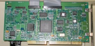
Which version of the 1006 controller do you have? I used a lot of the 1006s and I seem to remember that it doesn't matter what the drive type is set to--type 1 was usual. The BIOS on the 1006 patched in the proper parameters once you did a LLF.
Chuck(G)
25k Member
I think you mean WD1006V-SR1 (floppy-less version of the the -SR2). At any rate, are you sure there's no BIOS? These boards are all SMT with the BIOS in an unsocketed PLCC in an OTP 27C64. Look at the IC just below the header for the activity LED on the extreme left side of the card--a 32-pin PLCC 27C64.
The BIOS address for this card's LLF code is CC00:5, not C800:5, as on other controller cards and cannot be changed.
The BIOS address for this card's LLF code is CC00:5, not C800:5, as on other controller cards and cannot be changed.
Druid6900
Veteran Member
Is there a reason that you don't want to format the drive as RLL?
Perhaps there is already data on it and you just want to add to it?
The 251-1 will reliably operate as a 60 MB on a RLL controller whereas the 251 or 251-0 (same thing) won't.
People used to use the 251-1 all the time as a 60 MB unit and ran them that way until they retired the machine without any ill affects.
MikeS
Veteran Member
I think the BIOS can be completely disabled though, with W2.I think you mean WD1006V-SR1 (floppy-less version of the the -SR2). At any rate, are you sure there's no BIOS? These boards are all SMT with the BIOS in an unsocketed PLCC in an OTP 27C64. Look at the IC just below the header for the activity LED on the extreme left side of the card--a 32-pin PLCC 27C64.
The BIOS address for this card's LLF code is CC00:5, not C800:5, as on other controller cards and cannot be changed.
Chuck(G)
25k Member
I think the BIOS can be completely disabled though, with W2.
Yes, but you're not going to run that thing as non-RLL; the chipset doesn't support plain MFM. So you might as well use the BIOS.
One interesting aspect of this controller's BIOS is that it allows access to drives with more than 1024 cylinders--it borrows the upper couple of bits of the DL, the head register for that purpose. It can come in handy if you're using something like an XT1140 drive with 1224 cylinders.
Many thanks for all the replies on this!
I'm think the controller BIOS has been integrated into the system board BIOS; Amstrad fitted these via recall in some cases and in units produced after (the problem was identified), whilst (eventually sucessful) legal wranglings with Seagate were on-going so I guess cost was a big concern. Here it is:

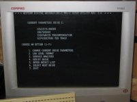
However I didn't know about the CC00 mapping, Amstrad instead supplying a little utility to supposedly low-level format the drive (no ability to enter error map though, and it fails with the ST-251-1 attached), however issuing the debug command does yield the BIOS utility:

So I'm not sure where this leaves me - note the mad values (drive type 50 per BIOS working perfectly meanwhile). I might get the courage to try it later.
I'm think the controller BIOS has been integrated into the system board BIOS; Amstrad fitted these via recall in some cases and in units produced after (the problem was identified), whilst (eventually sucessful) legal wranglings with Seagate were on-going so I guess cost was a big concern. Here it is:

However I didn't know about the CC00 mapping, Amstrad instead supplying a little utility to supposedly low-level format the drive (no ability to enter error map though, and it fails with the ST-251-1 attached), however issuing the debug command does yield the BIOS utility:

So I'm not sure where this leaves me - note the mad values (drive type 50 per BIOS working perfectly meanwhile). I might get the courage to try it later.
Last edited:
Chuck(G)
25k Member
If the whole EPROM is there at CC00, I'd give it a try.
Quick update - I put the original 40MB RLL drive back on the WD controller, ran Speed-Stor and it picked up all the errors on the sticker and blocked them out. Then it started reporting cyl 0 errors. Even when manually removed, the drive couldn't be formatted in DOS - 'track 0 bad'. So trying the CC00:5 utility, manually set the parameters then LLF/verify/enter error map, after which all is working well, much better indeed than ever before!
So tomorrow I might try and hook up the ST-251-1 and see what happens. I don't get the relationship between the Amstrad PC2286 BIOS and the WD BIOS, or indeed WTF the Amstrad LLF utility actually does.
So tomorrow I might try and hook up the ST-251-1 and see what happens. I don't get the relationship between the Amstrad PC2286 BIOS and the WD BIOS, or indeed WTF the Amstrad LLF utility actually does.
Just got a few minutes to test the ST-251-1 on the RLL controller as suggested, 26 SPT configured via cc00:5 utility.
Initial results are confusing. LLF ran fine, but strangly so is the WD controller's five-pass pattern test. So far (25%) 5 errors picked out with it in MFM configuration on the ST-11M haven't shown through - including one factory defect.
Does the RLL controller use a stronger write current perhaps? Or could it be that the 5150 I was using before might not have enough guts on it's 12V line (original 63W PSU)? Or something else...
Chuck(G)
25k Member
It's quite possible that RLL 2,7 encoding works just fine--the R/W circuitry has to be a bit more tolerant. I think I also remember that the 1006 allows for 25 SPT, for sparing.
Chuck(G)
25k Member
Now that is just plain bizarre--I could understand 31 spt if it was an ARLL controller, otherwise the data rate would be way out of bounds for most MFM drives but the 1006V, to the best of my knowledge is just a RLL (2,7) controller.
Give it a try and let me know.
Give it a try and let me know.
Chuck(G)
25k Member
Will do! (tomorrow though). Any risk of damage to the drive pushing it that far?
Nope, it'll just be the data that's all fouled up. MFM drives don't care what you try to write to them--they're very stupid.
MFM drives don't care...they're very stupid.
Suits me then
LLF pattern test finished with a bunch of errors identified on the inner tracks..., and crucially, one in what the ST-11M controller was using as the relocation zone. So hopefully I can now get a completely bad-sector free format on that controller.
But first I want to test the drive at the even higher SPT. At 26SPT, it had about 400KB of bad sectors (<1%).
Something else I was pondering on, presumably the 820 cylinders defined by the drive spec allow plenty of space for head parking etc. I wondered if (perhaps, how much) the cylinder count could be increased (for the ST-251-1), without damaging the drive?
Chuck(G)
25k Member
Well, I wouldn't recommend it. The area outside of the main usable area isn't checked by the manufacturer for usability and--this is the most important--inner cylinders are harder to read and write to. Because they're shorter (think of the inside lane on a race track) bits are packed tighter, which leads to issues such as bit-shifting that the controller can only partly compensate for.
And since the linear velocity is slower, the read signal is lower (signal strength varies as the square of the linear velocity). This is one reason that manufacturers never used the innermost cylinders for critical data storage, such as file directories or allocation maps--they're simply not as reliable, so it's only fitting that they're the last to be used.
But hey, it's your data. You won't wreck the drive by going overboard. At some point either the electronics or mechanicals will stop you.
Trixter
Veteran Member
Chuck, can you explain "engineering cylinders"? I've always thought they were one or two "hidden" cylinders past what was published by the drive, but I've never found a formal definition.
