• Please review our updated Terms and Rules here

Differences between IBM CGA cards

reenigne

Veteran Member
Joined
Dec 13, 2008
Messages
717
Location
Cornwall, UK
Anybody know what the difference is between the various IBM CGA card part numbers? I know of four: 1501486, 1504910, 1501981 and 1501982. The one I have is a 1501486 and as far I can tell the circuit is the same one as in the XT Technical Reference Manual ibm_techref_v202_3.pdf available from http://www.retroarchive.org/dos/docs/index.html, even down to the composite DAC resistor values being 3.3K, 13K, 5.6K and 2.2K. It looks like the ones at http://oldibmpc.sitesled.com/Expansion cards/IBM Corp.html, except the board is red instead of green.

I found a high-res image of a 1501981 at http://www.yjfy.com/museum/video/Video_8-bit_ISA.htm and it looks identical as far as the logic is concerned, but there are a few more resistors and the resistor values look different. I'm wondering if they were changed to make the composite signal adhere better to the NTSC standard and therefore be more consistent between different monitors, but that's just a guess.

The only other CGA schematic I've found is the one in IBM_5150_Technical_Reference_6025005_AUG81.pdf available from http://www.minuszerodegrees.net/manuals.htm#IBM but that doesn't list any resistor values.

Anybody here have any more information? If you have a CGA card with part number other than 1501486, I'd be interested in running some tests on it, especially if it's connected to a composite monitor. Thanks!
 
The circuit diagram in the Options and Adapaters manual shows DAC resistor values (R5/R6/R7/R8) of 680, 1K, 680 and 750.
And R1 (transistor emitter) there is 75, instead of 100.

Ooo, thanks - I had somehow managed to completely overlook the Options and Adapters manual.

That's really interesting - it seems that this version of the the CGA doesn't include the -BLANK signal in the composte output, but does include the "G OUT" (green) signal, which is another way (other than the resistor values) that the composite colours will differ between CGA versions.
 
Awesome - thanks again, modem7.

Based on the evidence I've seen so far, the chronology seems to be this:

The first CGA card was the 1804472 with the black bracket. This is the one whose schematic is in ibm_techref_v202_3.pdf. It has 7 resistors in the composite output stage (plus 1 for the ROM for a total of 8).

Next came the 1501486 (PCB number 1501453). This has the addition of four 30 ohm resistors for the digital output pin header, and moved the digital output pin header slightly to accomodate the new mounting bracket. It also has 7 resistors in the composite output stage (12 resistors altogether).

Then I think was the 1504910, and I think this is the one whose schematic is in IBM_5150_Technical_Reference_6025005_AUG81.pdf (but I'm not completely sure, I haven't seen an image of this board or of a board with this schematic). This schematic doesn't show the 30 ohm resistors, but I suspect that is an oversight and that they'll be on the board since they were there on the earlier 1501486. This schematic adds the red, green and blue signals onto the composite output so that if you're using a monochrome composite monitor you'll get 16 shades of grey instead of 4. There are 9 resistors in the composite output stage in this schematic (probably 14 altogether). With this change, there are now two resistors instead of three at the emitter of the transistor. These seem to be relatively rare.

Finally came the 1501981 (PCB number 1501982), whose schematic is in OA%20-%20IBM%20Color%20Graphics%20Monitor%20Adapter%20(CGA).pdf. This has several more changes to the composite output stage: the removal of the -BLANK signal, a 75 ohm resistor instead of 100 ohm on the emitter of the transistor and resistors between the base of the transistor and the 0V and +5V lines (130 and 360 ohms respectively). These had 10 resistors in the composite output stage (15 altogether). Some of these had a HD6845P CRTC instead of the usual MC6845P.
 
Last edited:
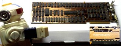
robot cga.jpg I just so happen to have two I believe, have yet to tear open my 5150 to see if the other matches, I think it is green though, this one is my backup! (Came out of my 1st 5162, believe its the stock) :D

BTW, this is a 1501981APS.
 
Last edited:
Perhaps the 1504910, which adds more gray shades would likely be seen in stock IBM PC Portables, as it had the mono composite monitor built in. But wouldn't adding the red, green and blue signals directly on the composite output change the color in some way?

Awesome - thanks again, modem7.

Based on the evidence I've seen so far, the chronology seems to be this:

The first CGA card was the 1804472 with the black bracket. This is the one whose schematic is in ibm_techref_v202_3.pdf. It has 7 resistors in the composite output stage (plus 1 for the ROM for a total of 8).

Next came the 1501486 (PCB number 1501453). This has the addition of four 30 ohm resistors for the digital output pin header, and moved the digital output pin header slightly to accomodate the new mounting bracket. It also has 7 resistors in the composite output stage (12 resistors altogether).

Then I think was the 1504910, and I think this is the one whose schematic is in IBM_5150_Technical_Reference_6025005_AUG81.pdf (but I'm not completely sure, I haven't seen an image of this board or of a board with this schematic). This schematic doesn't show the 30 ohm resistors, but I suspect that is an oversight and that they'll be on the board since they were there on the earlier 1501486. This schematic adds the red, green and blue signals onto the composite output so that if you're using a monochrome composite monitor you'll get 16 shades of grey instead of 4. There are 9 resistors in the composite output stage in this schematic (probably 14 altogether). With this change, there are now two resistors instead of three at the emitter of the transistor. These seem to be relatively rare.

Finally came the 1501981 (PCB number 1501982), whose schematic is in OA%20-%20IBM%20Color%20Graphics%20Monitor%20Adapter%20(CGA).pdf. This has several more changes to the composite output stage: the removal of the -BLANK signal, a 75 ohm resistor instead of 100 ohm on the emitter of the transistor and resistors between the base of the transistor and the 0V and +5V lines (130 and 360 ohms respectively). These had 10 resistors in the composite output stage (15 altogether). Some of these had a HD6845P CRTC instead of the usual MC6845P.
 
Perhaps the 1504910, which adds more gray shades would likely be seen in stock IBM PC Portables, as it had the mono composite monitor built in. But wouldn't adding the red, green and blue signals directly on the composite output change the color in some way?

It won't change the composite colours in the normal BIOS mode 6 with palettes 8, 7 or 15 (except possibly for a difference in brightness and/or contrast), but it will change the other composite colours.

According to my calculations, the composite output for 1501486 is approximately 0.72*CHROMA + 0.28*I, giving levels of (0, 0.28), (0, 0.72) and (0, 1) with those three palettes respectively.

The composite output for 1501981 is 0.29*CHROMA + 0.32*I + 0.07*B + 0.22*G + 0.1*R, giving levels of (0, 0.32), (0, 0.68) and (0, 1) respectively (since CHROMA=R=G=B for these palettes).

I'll make a new version of my all-modes, all-palettes CGA colour chart to show all the differences between the two major CGA versions.
 
Look forward to it. I assume when you mean "palettes 8, 7 or 15" you mean dark gray, light gray and white, respectively. Palette 0 is obviously black. I assume games used white to offset any darkening from the composite video. I have never heard of a game using one of the remaining actual color choices for the foreground, but it is not impossible.

Do you think its possible to implement something like a color chart to run on a vintage machine?
 
I assume when you mean "palettes 8, 7 or 15" you mean dark gray, light gray and white, respectively. Palette 0 is obviously black. I assume games used white to offset any darkening from the composite video.

Right, right and right.

I have never heard of a game using one of the remaining actual color choices for the foreground, but it is not impossible.

Yeah, I'm kind of surprised that they didn't - some fantastic lighting effects could have been done by changing the palette register to simulate changing the colour of the incident light.

All the games which use 320x200 modes will have different composite colours on the different CGA cards, though.

Do you think its possible to implement something like a color chart to run on a vintage machine?

Yes, and in fact that's exactly what my icon is a picture of (mode 6, colour burst enabled, 1501486 with a palette change every 12 scanlines). The program should work on any machine which implements the CGA status register correctly - I'll convert it to a .com file so others can run it more easily (at the moment it requires my keyboard port code loader hack) and make it do the other modes as well.

I'm also tempted to make a modification to my 1501486 to add a second composite output which duplicates the 1501981 DAC so I can calibrate my simulation of that too.
 
I am not sure how widely known it was that you could change the pixel color in Mode 6. It is obliquely mentioned in the first version of the IBM PC Tech Reference (which also mentions using IRQ2 for vertical retrace). I know that Sierra did release some of its SCI0 or SCI1 16-color games with a mode 6 driver that used blue instead of white, but the color burst is not enabled. http://vogons.zetafleet.com/viewtopic.php?t=9765&postdays=0&postorder=asc&start=180
 
Okay, I've put a little program at http://www.reenigne.org/misc/chart.com that displays the chart as shown in my icon and cycles through all the graphics modes (and foreground palettes for 320x200 modes) when you press a key. Pressing Esc should take you back to DOS. I haven't actually tried it in DOS yet, so it might be broken if the timer interrupt takes too long, and/or exiting to DOS might be broken.
 
I tried the program on my Tandy 1000SX on an RGB monitor using MS-DOS 5.0. The program works correctly and exits correctly. It does not quite work correctly in DOSBox. It cycles through eight screens :

1a00 - Mode 6 All Foreground Colors Color Burst Enabled
1e00 - Mode 6 All Foreground Colors Color Burst Disabled (identical to Color Burst Enabled on RGB monitor)
0a00 - Mode 4 Palette 0
0e00 - Mode 5 Palette 0 (identical to Palette 1)
0a10 - Mode 4 Palette 0 Intense
0e10 - Mode 5 Palette 0 Intense (identical to Palette 1)
0a20 - Mode 4 Palette 1
0e20 - Mode 5 Palette 1 (identical to Palette 0)
0a30 - Mode 4 Palette 1 Intense
0e30 - Mode 5 Palette 1 Intense (identical to Palette 0)

1a/1e/0a/0e - Value in Mode Control Register
00/10/20/30 - Value in Color Select Register
 
Works just fine with my IBM PC 5150 with a 1501981 CGA card. So many colors!

Numbers across top represent either background color (Modes 4-5) or foreground color (Mode 6).
 
Oh good.

I'm not surprised it doesn't work in DOSBox - changing the mode register on specific scanlines is a rather unusual thing to do, as is using graphics modes with the CRTC registers set up for text mode (8 scanlines per character row). I'm surprised it does as well as it does, though - it does successfully switch palettes every 12 scanlines.

I've updated the CGA colour chart with a couple of fixes - one minor one (colour 8 is darker) and one major one (corrected the gamma, so everything's darker). I've second CGA colour chart for the 1501981. Comparing the two side by side, lots of differences are apparent but they really all come down to the chroma colours having different lumas. This is particularly noticable when the colour burst is disabled because in that case the chroma colours look all the same when they don't have different lumas.

The 1501486 chart still doesn't look quite the same as the colours on my machine - I think some of the chroma waveforms are shifted slightly due to logic delays which, while much less than a clock cycle, still correspond to a visible difference in colour.

I might rearrange these charts so that the digital ouptuts, monochrome composite outputs and colour composite outputs are not interspersed - it'd probably be easier to understand and would correspond to the output of the chart.com program.
 
A comparison of the chart leads to some interesting differences. The 1501486 seems to show more colors and brighter ones generally, while the 1501981 shows more grayscale shades. It seems like each is best suited to a particular type of monitor.
 
The IBM PCjr. also supports color through the composite video port, but the logic from the Technical Reference to get there seems much more straightforward than on any CGA board. I know it supports 16 shades of gray and obviously direct color, but does it even support artifact color?
 
The IBM PCjr. also supports color through the composite video port, but the logic from the Technical Reference to get there seems much more straightforward than on any CGA board. I know it supports 16 shades of gray and obviously direct color, but does it even support artifact color?

I think it must do. I just checked the PCjr Technical Reference manual and it uses a gate array to replace much of the CGA's discrete logic, but there is a composite colour output signal, and the composite DAC output stage looks pretty similar to the 1501981 version, though the resistor values are slightly different (750, 1.1K, 2.2K and 3.3K instead of 680, 1K, 2K and 3K for I, G, R and B respectively).

I'm sure it supports artifact colour because (given that chroma colour works) it's harder to make artifact colour not work than it is to make it work. I'm not sure whether it uses the same color burst phase as CGA or as Tandy 1000 though (or even something else entirely).
 
Thumbs up for an interesting (and useful!) thread, folks.

reenigne said:
I just checked the PCjr Technical Reference manual and it uses a gate array to replace much of the CGA's discrete logic, but there is a composite colour output signal, and the composite DAC output stage looks pretty similar to the 1501981 version, though the resistor values are slightly different (750, 1.1K, 2.2K and 3.3K instead of 680, 1K, 2K and 3K for I, G, R and B respectively).

Check out this video at approximately 07:47 - http://www.youtube.com/watch?v=s5a6jKUkjlA
The 16 color bars on the PCjr boot screen show the same effect as the 1501981, so that looks right.

Perhaps the 1504910, which adds more gray shades would likely be seen in stock IBM PC Portables, as it had the mono composite monitor built in.

Not my photo (credit goes to RJBJR from this forum), but here's what the output looks like on a 5155 Portable:


Looks just like the older CGA revision (1501486), with the "greys" being the same. Interestingly, the PC Portable was released only one month before the PCjr, but there could have been minor revisions of both.
 
Back
Top