• Please review our updated Terms and Rules here

Kaypro II

Do you have a place near you that carries incandescent bulbs for autos? They're great for making dummy loads. I like the so-called "festoon" bulbs.

Something like a 211 lamp will draw about an amp at 12V and about the same at 5V, which should be enough of a load.

I have an Audi bulb in it's little holder but I'm going to the store to get some wire etc tomorrow.
 
So to clarrify you want the readings at the pins on the logic board when the power board is powered on and connected to the logic board?
No, we want to know what the voltages are on the +5V and +12v pins on the power supply when it is disconnected from the system board and a light bulb or similar load is connected instead between those pins and the common.

I'm a little confused; you said
I disconnected the power connector from the logic board and the values read are as follows:
-12 is reading -3.51v
+12 is reading 0.03v
+5 is reading 0.18v
and then you said
Testing the PSU on its own not connected to anything its still chirping.
The -12v pin is stable at -12.5v .
The +12v is varying constantly between about 7v and 12v by the look of it.
Similarly the +5v is varying between 3.8v and 5v or so.
Sounds like the PS is disconnected in both cases but the voltages are different?

Be careful; everyone warns about the high voltage on the CRT, but the really dangerous currents are in the power supply.
 
Last edited:
Ok. Cables made up nicely :) Power supply board removed from unit, and connected to mains supply, and a car headlight bulb connected across the 5V and Gnd pins of the power supply board.

Readings:

5v reads 4.81v
12v reads 13.64v
-12v reads -12.40v

No chirping. All steady.

Same bulb connected across the 12V and Gnd pins of the power supply board.

5v reads 3.8v
12v reads 0.30v
-12v reads -4.8v

PSU chirps happily at high speed.
 
That sounds pretty well as you'd expect, Usually the supply will monitor the 5V rail & adjust itself so that that is ok & the other voltages follow as best they can. 5V is a little low (still within TTL spec), it could be the smoothing capacitors on the 5V rail & if you can get a ripple measurement (in the absence of a scope try AC Volts on your meter - It should work but it won't be dead right because the meter is set to measure RMS (on a sine wave at about 50 Hz too)) but if it's less than 0.25V (RMS) you should be just about ok.
 
Okay, now let's go back to your motherboard.

FIrst of all, verify the connection between the +5 pin on J7 and pin 8 on any 14-pin DIP on the board. Should be very clear continuity. If not, inspect the solder connections for J7 (where the cable from the power supply plugs in). Make sure that it's good--and trace the +5 as far as you can.

If that all checks out, check the cable that goes from the power supply to the motherboard.
 
Are you sure you mean J7 and not J5? J5 is the connector where the PSU connects to the motherboard. J7 is a 3 pin connector where none of the pins are marked. (Just checking)
 
Last edited:
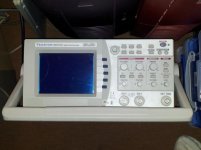
With the power supply board removed completely from the machine I connected the power board to the mains, and applied my bulb as a load on the 5v rail. I then connected my scope across the 5v and ground rails on the power board:


When I press "Measure" the scope tells me I have a Pk-Pk of around 13mV.

Am still examining the logic board.
 
Last edited:
FIrst of all, verify the connection between the +5 pin on J7 and pin 8 on any 14-pin DIP on the board. Should be very clear continuity. If not, inspect the solder connections for J7 (where the cable from the power supply plugs in). Make sure that it's good--and trace the +5 as far as you can.

Ok so you mean J5 rather than J7. Are you counting your pins anti-clockwise from pin 1?
 
I'm guessing what you call pin 8 is the opposing pin in the pair with pin 1 - although according to Wikipedia thats actually called pin 14???

Anyway, assuming we are talking about the same pin, every 14-pin DIP on the board with the exception of one has this pin connected to 5v. The one exception being U68 which appears to be a MC1488N, and its pin connects to the 12v pin.
 
Hope I didn't offend or insult anyone; just expressing my frustration following these 50 posts and the confusion, contradictions, etc. that this kind of troubleshooting often entails (not to mention the confusion of Kaypro model numbers).

Can we finally take it that the power supply is functional and in fact has been all along?
I.e.:
With nothing connected to the PS except AC in, the 5V and 12V outputs read ~3-5 and ~7-12V respectively.
With a light bulb across the 5V, the 5V output reads a steady ~4.5-5V, the bulb glows dimly, and +12V and -12V are also close.
With the system board connected the 5V and 12V outputs read close to 0.

Is that correct?

Notice that the scope is set to measure AC voltage, i.e. just the noise on the 5V line.

When you measure resistance to ground on the 5V, +12V and -12V pins on the system board when disconnected from the PS, you get infinite resistance on the 12V lines and around 300 Ohms on the 5V line? What range? In both directions?

When you're talking about P5, P7 etc. and Wikipedia, which schematics are you/we looking at? I thought the PS connector is a straight in-line connector, so what's the [counter]clockwise referring to? And pin 8 of the 14-pin DIPs?

The schematics I'm looking at call the power supply connector J7, as Chuck said; what and where is P5?

Assuming all the above is correct, let's finally see why the system board shuts down the PS. Have you inspected the usual culprits, any tantalum caps?
 
Last edited:
Sorry, I've been out wrestling with a chainsaw. I still have lots of cleanup to do from the snowstorm on the first day of spring.

At any rate, Mike, do you want to lead Chris through this? I'm having a problem assuming that Chris has some experience in this stuff. No offense to Chris, of course--I'm just not used to working this way.
 
Sorry, I've been out wrestling with a chainsaw. I still have lots of cleanup to do from the snowstorm on the first day of spring.
Ah the joys of living the life of the country gentleman in the rustic Northwest...
As a matter of fact I have a few downed trees as well, but they're a little big for me and my puny electric chainsaw.

At any rate, Mike, do you want to lead Chris through this? I'm having a problem assuming that Chris has some experience in this stuff. No offense to Chris, of course--I'm just not used to working this way.
Aw, don't go; once we straighten out what's what and are all on the same page looking at the same schematics it oughta be a breeze. Unfortunately my Kaypro is out on loan, but it's a 2x, somewhat newer; don't know how similar they are.
 
Ah the joys of living the life of the country gentleman in the rustic Northwest...
As a matter of fact I have a few downed trees as well, but they're a little big for me and my puny electric chainsaw.

Today I was out with my Stihl 056 Super--a beast of a saw, but it sure makes the chips fly. Big oak log shifted and broke the bar tensioning bolt, so it's out of commission until I get a new one installed. I have an 032AV, but it's being stubborn about not wanting to run. So it's back to the Mac 610--not in the same league, but it'll get the job done, just slower.

Aw, don't go; once we straighten out what's what and are all on the same page looking at the same schematics it oughta be a breeze. Unfortunately my Kaypro is out on loan, but it's a 2x, somewhat newer; don't know how similar they are.

From what I can tell, the 2X is pretty close in the mainboard department, but I'll have a close look at the schematics if there's any doubt. That 300 ohm continuity test Chris did on the +5 to ground on the motherboard doesn't sound right to me.
 
Hope I didn't offend or insult anyone; just expressing my frustration following these 50 posts and the confusion, contradictions, etc. that this kind of troubleshooting often entails (not to mention the confusion of Kaypro model numbers).

You didn't Mike - at least not me. I'm quite confused by this thread in points. Maybe at some points I've been far from clear, however I object the implication that I'm some kind of newbie made by Chuck. I've been using and working with computers since 1981 (as a teenager). I appreciate Chuck has been trying hard to help, and that it isnt easy in these situations, but I don't think I have been the only source of confusion.

Can we finally take it that the power supply is functional and in fact has been all along?

Whilst I think we have now established that replacing the electrolitic capacitors on the board was unnecessary, and that the board now appears to work correctly, the three X2 capacitors we definitely blown in the beginning - one to little pieces. I think we can say that despite peoples uncertainty that the Kaypro II powersupply does require a load.

I.e.:
With nothing connected to the PS except AC in, the 5V and 12V outputs read ~3-5 and ~7-12V respectively.
With a light bulb across the 5V, the 5V output reads a steady ~4.5-5V, the bulb glows dimly, and +12V and -12V are also close.
With the system board connected the 5V and 12V outputs read close to 0.

Is that correct?

Yes.

Notice that the scope is set to measure AC voltage, i.e. just the noise on the 5V line.

According to the guide I read on using a scope to measure ripple current they said thats what I should do because it effectively removes the +5v DC component from the signal, and accordingly allowed us to measure the degree of variance in the signal. I thought that is what Nige wanted me to do?

When you measure resistance to ground on the 5V, +12V and -12V pins on the system board when disconnected from the PS, you get infinite resistance on the 12V lines and around 300 Ohms on the 5V line? What range? In both directions?

I can do some more measurements in this area. To be honest I didn't think much about resistance because obviously a resistor isn't polarised - however thinking about it more there arent just resistors in the circuit we are measuring :(

When you're talking about P5, P7 etc. and Wikipedia, which schematics are you/we looking at? I thought the PS connector is a straight in-line connector, so what's the [counter]clockwise referring to? And pin 8 of the 14-pin DIPs?

The schematics I'm looking at call the power supply connector J7, as Chuck said; what and where is P5?

According to me, and clearly I may be wrong, this is the power connector, and it is called J5:
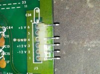
IMG_20120615_105415.jpg

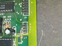
J7 looks like this:

IMG_20120615_105401.jpg

Now I don't have a pinout for this, but in my experience (which I'd say is fairly considerable) I wouldn't call this a power connector.

Now when it comes to counter clockwise counting, I was talking about the pins on a 14pin DIP (example included just to ensure we are talking about the same thing):
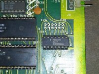
IMG_20120615_105529.jpg

According to the Wikipedia page, as we look at it in that photo the bottom left pin is pin 1 and you count counter clockwise for pin numbers making the top right pin number 8. Now from what I understood Chuck wanted us to check the continuity between the 5v pin of the power connector (which in my opinion is called J5 but this post may be proving me wrong) and pin 8 of each of the 14pin DIP chips. Continuity between the 5v pin of what I call the power connector, and pin 8 of the 14pin DIPs does not seem to be consistent at all - however there does appear to be continuity between the 5v pin of what I call the power connector and pin 14 of the 14 pin DIPs (i.e. the top left pin according to me) for all chips except one which I noted in a previous post where it's pin 14 (by my definition) is connected to the 12v pin of the power connector.

Assuming all the above is correct, let's finally see why the system board shuts down the PS. Have you inspected the usual culprits, any tantalum caps?
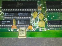
IMG_20120615_113403.jpg

If I'm right (and I admit to being unsure on this front), C8 and C9, which are a slightly more brown colour are tantalum cap, I count 10 on the board in total, none of which appear to have a problem (visually).

The other capacitors such as C82 (Ceramic disk caps?) is different. There are two, C53 and C59 which are damaged or at least cracked:
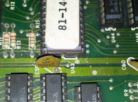
IMG_20120613_230622.jpg

I can go get replacements for these but I don't really know how to describe these or what spec they are.

Thanks for taking the time to read this, and thanks for all of each of your help with it.
 
Last edited:
Chris, it's not going to help if you feel we're talking down to you and you get defensive. We can only go by what we read in your posts and it does seem that despite your years of experience in using and working with computers you don't have a lot of experience in troubleshooting electronics. So what; let's not waste any more time on that and focus on solving the problem.

Regardless, it's challenging enough when you have the equipment and the tools and instruments in front of you but much more so when you have to do it through the eyes and verbal descriptions of someone else, and misunderstandings are almost inevitable.

The X2 caps were definitely bad and should be replaced, but they don't affect the operation of the power supply and weren't really relevant to finding the real problem with your Kaypro. As Chuck said, they (and also your real problem of the PS shutting down) are common problems and discussed in dozens of threads on this forum.

You have the board in front of you and you're right, the power connector is labelled J5. On the other hand, we only have the schematics to go by and on the ones I (and Chuck, presumably) looked at it is labelled J7 (or J2). Have you managed to find a schematic that corresponds to your board and if so, where?

Since the issue is that voltages drop to zero when connected, we're just interested in DC voltages and don't really care about noise or ripple; anything really severe would show on a DC scope trace anyway.

Except for the electrolytic beside J7, all the caps in your pictures including C8 & C9 are disk ceramics and almost certainly irrelevant.

What we need to do is find out which of the power supply lines is drawing too much current, and why; this can be challenging if there are no visible clues.

So, to confirm once more: with the system board only connected to the PS (i.e. no video, floppy drives, keyboard etc.) are the 5V and +12V lines close to zero?

I'd suggest powering the 5V and 12V lines separately, but I suspect that might damage the RAM chips; anybody else have an opinion on this?

Are the RAM chips in sockets? If so, can you remove them and check the voltages again?

So, please measure the resistances to ground of each supply line again, in both directions and tell us the lowest ohms range that gives you a reading, if any.
 
Last edited:
You have the board in front of you and you're right, the power connector is labelled J5. On the other hand, we only have the schematics to go by and on the ones I (and Chuck, presumably) looked at it is labelled J7 (or J2). Have you managed to find a schematic that corresponds to your board and if so, where?

Nope, only ones that call it J7 - I'm guessing in the same PDF documents you both have.

So, to confirm once more: with the system board only connected to the PS (i.e. no video, floppy drives, keyboard etc.) are the 5V and +12V lines close to zero?

I'll redo those tests on Sunday morning. I'm stuck in London tomorrow. What I'll do is put the power supply board and the logic board on the bench top, and do the tests using none of the actual Kaypro wiring. Thinking about it when I first tried stuff, the power board might have been effected by either the drives or the video card so by doing it externally it proves they aren't connected.

I'd suggest powering the 5V and 12V lines separately, but I suspect that might damage the RAM chips; anybody else have an opinion on this?

Are the RAM chips in sockets? If so, can you remove them and check the voltages again?

The RAM chips are socketed

So, please measure the resistances to ground of each supply line again, in both directions and tell us the lowest ohms range that gives you a reading, if any.

I'll re-do these resistances again on Sunday as well.

I appologise for getting grumpy with people. All my life I've had people bringing PCs to me to fix, and I admit until recently if I determined the PSU was playing up, I took the PSU out and fitted a new unit, as with the other parts of the PC. I did however do electronics qualifications but they were more than 20 years ago and havent been used in the meantime. I'd hope though that assuming I understand what people are saying I shouldnt need telling things more than once.
 
Back
Top