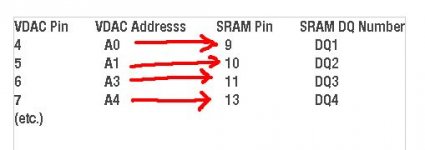
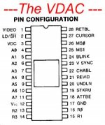
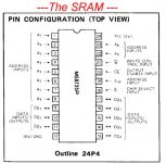
Leeb, I'm confused about which pin and chip you want me to measure voltage on. I have the pinouts for these and I can go to the right place. ") A5 on the VDAC, the socketed chip, is Pin 9 and it connects to Pin 15 on the SRAM, Data In/Out 6 (where the first one is #1, so yes, what you're counting as Data In/Out 5).
A5 on the VDAC, the socketed chip, is Pin 9 and it connects to Pin 15 on the SRAM, Data In/Out 6 (where the first one is #1, so yes, what you're counting as Data In/Out 5).
Just tell me again what to measure.
Re this: >> How many times can you overwrite before the input buffer fills and a new A:> comes up? <<
--the 128th character results in a new prompt. So you keep overwriting until then. The prompt itself, which I don't input, the A>, is included as two characters.
Same as what you said earlier.
On this: >> or perhaps a 244 for the A5 line is defective... IMO. <<
--you mean A5 on the VDAC?
thx,
Steve
A5 on the VDAC, the socketed chip, is Pin 9 and it connects to Pin 15 on the SRAM, Data In/Out 6 (where the first one is #1, so yes, what you're counting as Data In/Out 5).Just tell me again what to measure.
Re this: >> How many times can you overwrite before the input buffer fills and a new A:> comes up? <<
--the 128th character results in a new prompt. So you keep overwriting until then. The prompt itself, which I don't input, the A>, is included as two characters.
Same as what you said earlier.
On this: >> or perhaps a 244 for the A5 line is defective... IMO. <<
--you mean A5 on the VDAC?
thx,
Steve