• Please review our updated Terms and Rules here

Commodore 128 Power Supply Repair

KevinO

Experienced Member
Joined
Apr 13, 2012
Messages
380
Location
Des Moines, IA USA
I have a 128 power supply that I've been trying to repair, but it has so far eluded me. The schematic in the SAMS manual does not match this one. The one I have looks more like this one I found on zimmers:
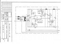
ps-128.jpg

The problem is that it has no values, and the board isn't labeled either. All I know is I've got about 30vdc on the emitter of what they're calling V6, (assuming this is the right schematic) and 3.4V on the collector. And what's that SCR/Zener thing doing over there on the right? No idea what that's for.

I've replaced the electrolytics, tested V6 and V7, and even replace the 78S40 chip, just for giggles. Measured all the resistors on the board, and they too are all correct.
 
Hi KevinO

I had a dead 128d supply that was caused by a shorted electrolytic capacitor.

Isn't the zener and scr a safety measure grounding the 5v dc if it goes over voltage? Set by the zener bleeding voltage on the gate of the scr turning it on and then shorting the voltage to ground thus saving the electronics!

If the scr has shorted it might be clamping the voltage down and also if the zener has broken down could have the same effect.
 
Last edited:
Shorting out the 5v line? That can't be right, although that's certainly what it looks like. Anyway, I replaced the zener and SCR, and that made no difference. I only had a few minutes to look at it last night, but I think the problem is in the V6-V7 area. I need to compare the voltages on those transistors to my known good PS, which I have not yet had a chance to do.
 
Offensive_Jerk what voltages do you have on your supply?

KevinO have you checked the traces on the PCB for cracks and the solder joints on the inductors L2 and L3 and on the transformer.
These seem to be common areas due to the stresses on the supply.

Have you changed all the electrolytics then? I have often found faults to be the simple things rather than IC's etc.
 
Yeah, I suppose I should have gone through all the things I had done first.

Check output of rectifier bridge-30vdc- same as good PS
Look for broken/cold solder joints
Look for burned glue, which can short out connections.
Replaced electrolytic capacitors (there's only 2 in this PS)
Tested transistors and diodes
Checked continunity on inductors and those funny jumper wires which are actually resistors?
Checked values on all resistors (in circuit)
Replaced the 3 big heatsinked devices: V6(transistor), V8(diode) and V10(scr), plus V9 zener.

Only then did I get silly and try the IC. I've replaced everything in the whole circuit except small caps and resistors! Oh, and because it can often be more than one thing wrong, I also put the parts from the bad PS onto my good donor PS, and the good one keeps working.
 
KevinO aren't there more than two electrolytics?
I thought there were around eight, there are a few smoothing capacitors that go across the 5v line.
They would also short out the supply if have gone short circuit.

Sorry getting it mixed up with the 128d that has around eight electrolytics, the 128 external has a few
smaller packaged capacitors those small rectangles, have you checked those?

The circuit schematic shows three electolytics c4, c9 and c10. Looks like c9 and c10 are for smoothing the inductors
and c4 smoothing after the bridge rectifier.
 
Last edited:
KevinO aren't there more than two electrolytics?
I thought there were around eight, there are a few smoothing capacitors that go across the 5v line.
They would also short out the supply if have gone short circuit.

Sorry getting it mixed up with the 128d that has around eight electrolytics, the 128 external has a few
smaller packaged capacitors those small rectangles, have you checked those?

The circuit schematic shows three electolytics c4, c9 and c10. Looks like c9 and c10 are for smoothing the inductors
and c4 smoothing after the bridge rectifier.

No, there aren't any more than the two electrolytics, so even this schematic must not be precisely correct. Without values, I have to trace everything out to see what's what. I think C10 is one of those square ones, and right now I have it out of the circuit, because I unsoldered L3. I did this to eliminate the possibility of there being a short in the cable. Still 3.4v on the 5V line!

The other rectangular caps could be bad, I suppose, but they're on the AC side of the transformer, so I don't think they are related, especially since I'm getting the proper rectified 30VDC out of the bridge.
 
KevinO I take it you have socketed the 78s40?

I wonder if it has to be set via R11 to set the output voltage! as it has an op amp in the chip.
Maybe due to chip tolerances, can you check the resistance on your working supply of R11 particularly
the mid setting and then compare it with the bad supply.(R11 may be used to set the output voltage.)

It may also be worth socketting your good supply to test the 78s40!

The voltages you are getting now, are they the same as before any component change?

After looking at a few 78s40 circuits they use a variable resistor to set output voltage so that could be the problem,
May just need calibrating using the variable R11 setting it with a screwdriver and meter to 5v.

To be on the safe side you could turn it slightly with the voltage off then connect to the mains to see if it alters the output voltage.

I don't want to teach your gran to suck eggs but be careful with the mains on as mistakes can have fatal consequences!
 
Last edited:
Finally got it fixed yesterday! Sorry I didn't post. Pet Rescue, you were on the right track. After swapping nearly every other major component with a good working PS, I had still gotten nothing but 3.3 to 3.5v as adjusted by R11. So I finally measured across R11, and got 1000 ohms on what was supposed to be a 200 ohm pot. Swapped out the pot from the good working PS (which was 250 ohms) and it's fixed!

I didn't have anything resembling a 200-250 ohm pot, so I measured each end to the wiper and then used static resistors to approximate the pot in the correct position. I ended up with 82 and 150 ohms, and ended up with an unloaded output of 5.16v, 5.05v under standard C128 load. It can't be adjusted this way, but usually they don't need adjusted once set.

This was a free C128 Power Supply I got from ECCC, so it's nice to have an extra one. I always seem to have more computers than power supplies, and my C128s are no exception.
 
Last edited:
Well done KevinO!

I've learned a little bit more looking at the circuit and blown some cobwebs off the old grey matter!
Takes me back to electronics in college again! Inductors leading capacitors lagging and all that!!
 
Back
Top