• Please review our updated Terms and Rules here

Any way to replace 5160/5161 power supply?

First of all, I can't thank you enough. If I could transform into an anime teenage girl and jump up and down clapping without seeming pervy, I would do that in a heartbeat.

Secondly, thank you for the close-up shots of what popped cold soldier joints look like, as well as what testing voltage with a multimeter looks like. I am less scared of electronics now, and if I had known that repairing popped joints was just a matter of heating up the soldier and reflowing it, I might have taken that on. In fact, I think the next time I have something like this happen, I will likely use it as an excuse to buy an iron and just give it a shot.
I'm glad you're happy, haha. It was quite a surprise after the repairs to the traces and reflowing the bad solder pads (I went ahead and added a little new solder too). At first I was just getting a bump from the fan, but no voltage longer than a split second. Then I figured the load I had may not have been enough. Attached another drive, and the fan ran for a good second, but still died. So then I tried a load that also took the -12v and -5v (a motherboard) and viola, the PSU ran and kept running. I also tested the voltages to make sure they were fine, and if I needed to, adjust it so it was within it's proper range. However, it was so perfect as it is, I didn't bother with adjustments. By the way, the PSU was dated inside under the PSU board, 1983. ;) It's 30 years old.

Some of the solder pads required more than reflowing. Some of them were literally ripped from the board, and required a wire that was the right gauge to handle the current, to basically reconnect the traces to their destinations.

I'm going to re-use the box you sent me, but put in more extra padding (you packed it very well but I just don't trust the USPS after seeing how badly torn those solder pads were).
 
Alls well that ends well:

02240003.jpg

I believe someone (bettablue?) is running some sort of 5161 owner's database, but I wasn't able to find it in the forum (searching '5161 database' breaks the search functionality)...
 
Jim, see here - doesn't look to be online yet.

If you do get a soldering iron, I'd suggest getting a temperature controlled station as the simple unregulated irons are next to useless - easy to burn the pads off circuit boards.
 
..as the simple unregulated irons are next to useless - easy to burn the pads off circuit boards.

Yep, that's very true. When I started soldering, that happened a lot. I use only temperature controlled ones now.

What becomes a pain though, is as I had to deal with Trixters PSU, heavy shock from shipping, caused solder pads from the heavy items like transformers, to literally be ripped off from the PCB. At that point, you have only one choice, to run a new trace, which is why there's some red wire in there now. I hate running new wire, but you gotta do it, if the pads are no longer there.

In this photo, you can see what I initially missed when I thought it was a capacitor issue, and explains why I thought the cap was bad. I was probing the cap from the points it connects too, not directly off the cap itself (which was a mistake on my part).

repair2_zpsda4129f4.png


That isn't just a cracked solder joint, that pad is just gone.

So what I did was this, for mechanical reliability. Now I couldn't do this on all of the problem points as you'll se later, but if you notice, there's two solder pads directly after it. They are on the same trace So I'll need to bridge them too with solder or wire. What I did, was took my wire, laid it across them all, and made a rock solid solder connection with the wire, as seen here.

repair3_zpsc279d7e9.png


That wire is not going anywhere, and it's only mating with the circuit it should be.

Now, as I explained earlier, there were some solder points that weren't so easy. This one as you see here, that solder pad was just, gone completely as above, but there was however nothing to solder also nearby on the same trace, to add mechanical reliability. While in this picture, it may not look secure, it actually is. What the picture isn't showing, is that the solder on the wire and that single pin from the transformer, is actually quite thick, and the pin is surrounded. Not too much, and not too little. I tested the reliability. I was not able to pull off that wire.. So as long as you don't play soccer with the PSU, that wire isn't coming off (and I don't think it'll even come off then!).

repair1_zpsa0b0e9f4.png


So yea, I do recommend a temperature controlled iron, but in the cases of where the solder pads are already missing, you're in a whole different ball park. ;)
 
...So yea, I do recommend a temperature controlled iron, but in the cases of where the solder pads are already missing, you're in a whole different ball park. ;)

Thanks for posting the video and these pictures btw - very interesting to see this type of damage. As for the missing pads, even then the temp.controlled station is the way - that chunky wire and large PCB traces can suck away the heat from a cruddy 15W Weller Special preventing the solder from running properly into the wire/joint. In my experience, anyhow :D
 
Thanks for posting the video and these pictures btw - very interesting to see this type of damage. As for the missing pads, even then the temp.controlled station is the way - that chunky wire and large PCB traces can suck away the heat from a cruddy 15W Weller Special preventing the solder from running properly into the wire/joint. In my experience, anyhow :D
Only soldering stations allowed here, none of those plug in things with no knobs, haha.
I honestly have no idea what the max temp of my soldering station is, but I sure wouldn't use the max, that'll lift pads quicker than you can say "crap!".

I used fat wire though on purpose. I thought about using a thinner wire to keep it more neat as possible, but really, this is high voltage areas that got damaged. I needed to use a heavier wire, so it was really about function rather than looks.

You can also see though in the 3rd pic, how some of the other solder points are extra shiny. Those were reflowed with some new solder added. If it looked like it "may" be bad, I just played it safe and gave it new solder.
 
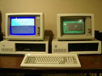
The one with dual hard drives is the 5161 expansion unit; the one with dual floppies is the 5160. The color monitor is connected to the 5160 and the MDA is in the 5161 (ie. each sits on top of their respective card placement).

I arranged cards so that if I wanted to work without the 5161 turned on, I could (the fan is noisy, I might replace it). Without the 5161 turned on, I get an 1801 (or 1861?) error on boot, but that's just the extender card saying it can't reach the receiver card. Press F1 and boot continues normally.

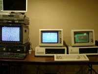
To blow your mind even further, here's the full setup with the third composite monitor attached:

02240004.jpg

This is my CGA graphics code running on the CGA and composite monitors, with the source/IDE/debugger running on the monochrome monitor. From April to September I'll be overhauling my graphics library for a display I'm putting together for VCFMW.
 
That photo is so confusing, haha. Which ones the 5161? And are both monitors on the same computer?
I think the 5160 is on the left with the 5153 driven by a CGA card and the 5161 with a MDA card driving the 5151 mono monitor. My question is, how are the two monitors able to display different images at the same time? I thought that only one monitor would be active at once with this setup?
 
Last edited:
I think the 5160 is on the left with the 5153 driven by a CGA card and the 5161 with a MDA card driving the 5151 mono monitor. My question is, how are the two monitors able to display different images at the same time? I thought that only one monitor would be active at once with this setup?

MDA works at a different memory address to the colour cards, so unless you intentionally clear the memory then there is no reason for it to go blank.
The little dual screen trick was quite handy at times - especially if you needed a reference table (for a game or whatever) and didn't have a printer hooked up.
 
How would you get them to show stuff though, if your in a CGA game? How do you pull up something on the MDA? I would think if you say opened up an app for MDA like a text editor, when you quit, it would go blank and whichever display had the DOS prompt, would be the only one to show a prompt.
 
There may have been utilities for doing this explicitly, but it's really easy using just DOS:

Code:
REM switch to monochrome screen being active
mode mono
type cheats.txt
REM switch to color screen being active
mode co80
REM mono screen is NOT erased!  Still shows prior contents!
mygame.exe

Adventure game walkthroughs are a good reason to try this :)

I actually use them for what they're meant for: Debugging. I run "turbo /d" while color is active, and the Turbo Pascal IDE shows up on the monochrome monitor. I can then write code, single-step through it, watch x86 registers change, etc. all while my graphics code is producing graphics (or gibberish) on the color screen. Turbo Debugger supports this too but the command-line is different.

Lotus 1-2-3 supported dual monitors; work on your spreadsheet in mono while generating graphics in color. Tweak a number, see the graph change.

Sadly, I can't think of any other software for x86 that used them effectively -- surely there must have been more, but I didn't focus on applications much in the 1980s.
 
Last edited:
How would you get them to show stuff though, if your in a CGA game? How do you pull up something on the MDA? I would think if you say opened up an app for MDA like a text editor, when you quit, it would go blank and whichever display had the DOS prompt, would be the only one to show a prompt.

One detail I wanted to add was that when I used it in practice (exactly as per Trixter's post) I'd make a text file of about 20 lines with the stuff I needed. So TYPE would leave the entire contents on the screen. It sounds fiddly, but I didn't have a printer, so it was a godsend!
 
Back
Top