• Please review our updated Terms and Rules here

Fixing a VT52: any paper schematics?

Xezlec

Member
Joined
Sep 29, 2009
Messages
31
Location
Austin, TX
Hello all,

I've just added a thoroughly nonfunctional VT52 to my terminal collection. I would rather have a thoroughly functional VT52.

The beast does show a (terrible) raster image on the CRT as it is supposed to when the brightness is turned up enough, but no characters, and more ominously, pressing keys produces no click, nor does Ctrl-G sound the buzzer when set to local echo mode. So, basically, no sign of a brain. So far, I've checked all the power supply voltages, and they're what they should be.

Since the symptoms (to me, at least) suggest a logic board issue, I feel like I should grab a scope and dive into that. The thing is, the VT52 schematics from the internet don't seem to include a diagram showing the physical layout of the components on the main ("data path") logic board. They have layout diagrams for the other boards, just not the main one. I'm not sure if this is an omission on the part of DEC or whoever scanned the field maintenance print set. Also, the resolution on this scan is so unbearably awful that it is virtually impossible to read the labels on any of the components in the layout diagrams.

So what I'm getting at is: does anybody happen to have a paper copy (or a good, high-resolution scan) of the VT52 field maintenance print set? Also, any other pointers would be welcome. Otherwise, I'm just going to have to pull everything apart, follow all the traces, and make my own diagrams. :(

Thanks for any help!
 
One of my VT52s failed in a way similar to yours. The problem was the TTL clock oscillator at E1 (13.824 MHz.) It had failed completely. I had another one made (the frequency is custom unfortunately) and the terminal has worked fine since.

Lou
 

Those are the internet ones I was talking about.

One of my VT52s failed in a way similar to yours. The problem was the TTL clock oscillator at E1 (13.824 MHz.) It had failed completely. I had another one made (the frequency is custom unfortunately) and the terminal has worked fine since.

Oh, thanks for the tip! I'll check that out first then.
 
...The thing is, the VT52 schematics from the internet don't seem to include a diagram showing the physical layout of the components on the main ("data path") logic board. They have layout diagrams for the other boards, just not the main one. I'm not sure if this is an omission on the part of DEC or whoever scanned the field maintenance print set. Also, the resolution on this scan is so unbearably awful that it is virtually impossible to read the labels on any of the components in the layout diagrams...

Those are the internet ones I was talking about.
Ok - I see the problem exists on the Bitsavers versions. In fact, all the web versions of that print set seem to come from the same scan. Schematic pages are mostly readable, but the component layout diagram for the data board is missing or not included.

I'll look through Fiches and Hardcopies - will post back.

UPDATE:

I have on Fiche:

  • DOL and FCO's for VT52
  • Module information for the Data Module 54-11745 including Layout, Artwork and updated Schematic
  • Plus other TMs already online

Please verify you have the 54-11745 board before I take the time to transfer from Fiche. I can't promise "stellar" resolution, as my reader has about 1/2 the magnification it needs for this. However, I have produced useful documents before and since there's no layout at all in the maintenance prints for this, I expect you'll want me to try.
 
Last edited:
Please verify you have the 54-11745 board before I take the time to transfer from Fiche. I can't promise "stellar" resolution, as my reader has about 1/2 the magnification it needs for this. However, I have produced useful documents before and since there's no layout at all in the maintenance prints for this, I expect you'll want me to try.

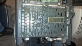
Yeah, that's good to hear! I can't find a number on the front of the board, and I can't seem to get to the back yet (I need a special tool to turn one of the fasteners open that I need in order to get down in there). But if it looks like this photo, it's close enough for me. 2013-03-11_21-54-17_615.jpg
 
Grrr...

After much experimentation, it is clear that I need to obtain a higher power lens for the level of detail required for this.

PM with Link Sent - Look at what I have to see if it's helpful at all.

  • TIF images are originals [perhaps you can make something of them?]
  • JPG images are the processed versions - enhanced to bring out detail [not pretty]


None are great. See if you can make them do.

I don't want to invest any more time doing other boards if these won't. I'll look again for another lens - getting detail from this one is futile. (It barely makes the page 1/4 of my reader's screen)
 
Last edited:
Obtained a 42x lens today. Will post better results after your feedback.

I can confirm that the layout does match your board.
 
Wow, thanks for all your trouble! I didn't mean to make your life difficult.

Yes, those are decent enough; I can at least make out most of the numbers.
 
One of my VT52s failed in a way similar to yours. The problem was the TTL clock oscillator at E1 (13.824 MHz.) It had failed completely. I had another one made (the frequency is custom unfortunately) and the terminal has worked fine since.

Finally had a chance to set up the scope, and sure enough, looks like the oscillator has decided to become a 4V voltage regulator.

You wouldn't happen to remember offhand where you got yours, and maybe what specs you gave them exactly, would you? Exactly mimicking whatever you did would save me the opportunity to get something wrong.
 
Wow, thanks for all your trouble! I didn't mean to make your life difficult.

Thanks for the appreciation, but you didn't cause anything. I've been trying to work towards a larger goal that would help me with all the fiches I have, and ignoring the problem of doing individual documents.

Not being sufficiently equipped makes it a PITA, and it's about time I did something about it. I never intended it to take so long to find an "ultimate solution". So a little detour that helps in the meantime - gives me back much more than it took.

Yes, those are decent enough; I can at least make out most of the numbers.

I was hoping that was so. Applying a "High Pass Filter" usually makes them legible, at the cost of photo realism. The new lens at least doubles the visual clarity, so with the same filter enhancements the result should be even better.

To share some details: I'm finding that the class of reader(s) I have are reaching their resolution limit because at the magnification levels I need, the system is not sufficiently achromatic. (possibly the lens, or maybe the mirrors or even the focusing screen) I can see the Red and Blue edges on letters and fine lines, before attaining the desired image scale. Another issue is the grain of the rear projection focusing surface - nowhere near fine enough. It creates noise in the image the more I enhance for detail. I've tried using a projection method to solve the grain issues, but that costs more photographic distortion. Too many tradeoffs. I have an old rear projection HDTV I may try to cannibalize into a better viewer. If a 57" image surface isn't big enough, then I might as well give up.

Anyway, I'm now thinking it will really take a higher class of reader. I need to go to the county library to "test" some better ones to make a good selection before buying the next (last?) one. Perhaps it will be a printer / scanner also. [getting tired of using a camera to shoot the screen] There seems to be no way to avoid a significant investment, so I might was well do the evaluations to make one I can really live with. :wallbang:

Then I can go back to my real goal of Whole Fiche Images. (The only practical way to share 7K+ fiches in one lifetime)


I'm going to have to clamp down on how I share the results too. Too many hackers now to risk my bandwidth on. I wonder if I could make an appeal to someone with connections, perhaps at Bitsavers, to be able to add my (our) contributions to their collection. Maybe someone will post here or PM me.

I'll re-shoot the fiche tonight and put up a new image, at least for comparison's sake. Are there any others from that board set that you'll need while I'm at it? [Lou - any suggestions?]


Finally - on troubleshooting techniques: Did you notice these in your internet travels?


These are the two best of the night.

Color is raw image, greyscale is processed for legibility.

DSCN5079.JPG


DSCN5079a.jpg


It's only a 3.5MP camera, and could use an 8.


It's aways something I guess.
 
I think that one missing page will be enough. I don't remember being bothered by that missing page in the past. It must have been six years ago that I last worked on the VT52. Although those component maps are nice, the ICs on dec boards are usually numbered somewhat sequentially starting from 1 in one corner. That's usually enough.

Somewhere along the way I got EK-VT52-MM (the maintanence manual). It's really good, like the one for the VT100. I'm not sure where it came from, but if the OP can't find it, he can send me a PM and I can e-mail a copy (7MB).

Lou

PS - Edit: I just saw the posting of the photo from the fiche reader screen. That looks good enough for me!

Also - where did you buy a fiche reader lens? I would like to get the wider lens for my NMI-75......
 
Xezlec was kind enough to remind me in a PM that I totally missed his post that he found his problem was also the E1 TTL clock oscillator. I answered his question about sourcing a replacement in a return PM, but I should post it here also for anyone else ever searching and finding this thread:

The oscillator is a TTL clock oscillator and has the standard four pin pinout for such devices. It has the pin arrangement of pins 1,7,8,14 of a 14 pin dip. If you look in any parts distributor's catalog you will see similar oscillators. But, you won't find this frequency in a ready made unit.

Up until about five years ago, companies that cut custom crystals made to order also used to make custom clock oscillators. Since I was a teenager (ham since age sixteen), I bought radio crystals from Jan Crystals. They custom cut the crystal and mount it in a can. They also used to custom make clock oscillators. You could order low quantity, the price was cheap, and you just waited four weeks until they ran your job. I probably paid less than $20 each for two custom clock oscillators that were made to order. Jan no longer makes TTL clock oscillators though.

However, Jan's competitor, Bomar, still makes them. I would try them next. http://www.bomarcrystal.com/oscillat...cmos_dual.html I have no idea what they would charge. But they can make it!

Lou
 
You can buy one-off custom programmed frequency oscillators from Digikey (and probably other sources too, like Mouser) but I have used Digikey recentlly.

See: http://www.digikey.com/scripts/dkse...wproducts=0&ptm=0&fid=0&quantity=0&PV183=6106

3.3V or 5.0V, CMOS or TTL, half or full size 4p DIP. About US$4.10 each in single unit quantity plastic dip. US$7.09 if you want a classic looking metal DIP package.

Don
 
Last edited:
Boy am I dumb! (And boy do I hate these PDFs.) I happened to look at the schematics again today, and suddenly realized that the chip I thought was labelled "E9" might actually be an "E8", and there was another chip that might be "E9"! (They both have a featureless black oval for the number.) So I tried that one and sure enough, there's the damn clock signal. Workin' fine. Well, if the oscillator ever breaks, I have a spare on its way to me now. :roll:

Guess I'll keep looking for the problem. But wow do I ever hate these PDFs.
 
... I thought was labelled "E9" might actually be an "E8", and there was another chip that might be "E9"! (They both have a featureless black oval for the number.)...

May I know precisely which document and page you mean here?

I'll see what I can do to help.
 
Oh, it was the same document (the VT52 schematics) but this time it's the layout diagram for the ROM, UART, and timing board (RUT).

Anyway, now I can see that the clock is running, and that the program address is changing in a regular way. It seems like keypresses are sometimes able to affect it too.
 
It's only a 3.5MP camera, and could use an 8.

Jeez! My phone's camera is 8. Even my previous phone, years ago, was 5. It sounds like your fiche collection is a real piece of history. I wish I could help in some way. Can you use just any camera?
 
Back
Top