Dear all,
I am (yet another) low-bit enthusiast living in Germany who recently dug out a Commodore Pet 2001 which I always wanted to repair and now the time has come. I'm not overly deep into electronics, though interested.
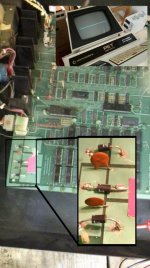
As you can see on the picture, the symptom is that there is no vertical deflection. The entire picture falls into a single line. Examined closely and with a low intensity setting of the screen, the line rather appears to be slightly dashed, so I would suppose it reflects a character pattern. So it must either be the screen or the board. Or both.
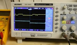
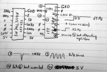
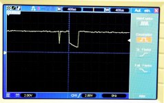
So rather than buying three working Pets I decided to buy one oscilloscope and track down the error by unplugging the video connection and measure the pins. The lower signal on the picture shows the horizontal sync at about 15.62kHz and 1.5V.
That signal can be used as a trigger for the video signal which can be seen on the upper half. The video signal is at about 5V, non-periodic. The oscilloscope was not quite sure about the frequency but it jittered around 1-3MHz which might well be the pixels.
The vsync pins yields a 4.5V DC signal actually with some 15.62 jitter around the 4.5V but I would supposed this is only line cross talk (cross over? - whatever you say).
Since I am doing that for the first time, did I make any false assumptions and if not, how do I get closer to the source of the problem.
Another thing: At the lower left of the board there are some coarsely replaced diodes. The uppermost points into another direction as compared to the lower two. Is this correct and on which circuit diagram can I find the layout of my board?
Hoping for an interesting discussion,
cheers,
Thomas
I am (yet another) low-bit enthusiast living in Germany who recently dug out a Commodore Pet 2001 which I always wanted to repair and now the time has come. I'm not overly deep into electronics, though interested.
As you can see on the picture, the symptom is that there is no vertical deflection. The entire picture falls into a single line. Examined closely and with a low intensity setting of the screen, the line rather appears to be slightly dashed, so I would suppose it reflects a character pattern. So it must either be the screen or the board. Or both.
So rather than buying three working Pets I decided to buy one oscilloscope and track down the error by unplugging the video connection and measure the pins. The lower signal on the picture shows the horizontal sync at about 15.62kHz and 1.5V.
That signal can be used as a trigger for the video signal which can be seen on the upper half. The video signal is at about 5V, non-periodic. The oscilloscope was not quite sure about the frequency but it jittered around 1-3MHz which might well be the pixels.
The vsync pins yields a 4.5V DC signal actually with some 15.62 jitter around the 4.5V but I would supposed this is only line cross talk (cross over? - whatever you say).
Since I am doing that for the first time, did I make any false assumptions and if not, how do I get closer to the source of the problem.
Another thing: At the lower left of the board there are some coarsely replaced diodes. The uppermost points into another direction as compared to the lower two. Is this correct and on which circuit diagram can I find the layout of my board?
Hoping for an interesting discussion,
cheers,
Thomas

")