• Please review our updated Terms and Rules here

PET 2001-8 Swap similar motherboards for testing?

snuci

Veteran Member
Joined
Nov 22, 2012
Messages
1,555
Location
Richmond Hill, Ontario, Canada
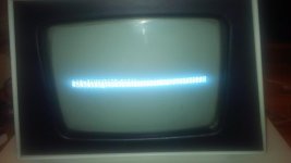
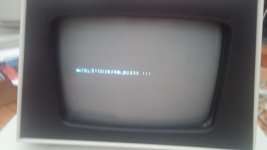
I recently acquired a PET 2001-8 with the fuse holder missing. The seller didn't know much about the machine (it was her brothers who left it in her basement) so I took a shot at it. I finally found a fuse holder (not similar to any other computer or PET I had) and fired it up. Below is a picture of the output. When the monitor fired up, it sounded like the degauss sound of a Sony monitor. I have another PET 2001-8 and I don't remember it doing that. The screen actually looks like it might be correct in terms of character place holders (with odd characters replacing them) and even has a flashing cursor but typing anything in does not move the cursor.
pet2001-8.jpg

Anyhow, the motherboard is a 320008 and I'd rather not mess with it until I have to. I have not reseated the chips as of yet. As I mentioned, I have another PET 2001-8 that has a 320137 motherboard. For troubleshooting purposes, can I swap motherboards and see if the older board works in the newer case and vice-versa? I don't think it should be a problem but I want to be sure. The power connector on J8 is slightly different and has an extra cable that doesn't appear to be connected on the working PET (it's odd and has a different longer connector). If so, I'll do it this weekend and see what happens.

I did some searching and couldn't find a similar issue. I also played with the vertical adjustment pot in the back of the monitor but that just moved what is displayed up and down. Any help is appreciated.
 
Interesting; AFAIK all four versions of the 2001-8 had identical power supplies and connectors, 5 pins arranged symmetrically so you could plug it in either way:

Transformer to the two outside pins (1 & 5), ground to the centre pin (3), filter cap positive to pins 2 & 4 and negative to ground (pin 3)

Can you describe the two connectors and specifically what is different?
 
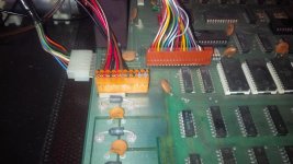
The earlier PET has the normal 5 pin molex connector. The newer 2001-8 ("Professional Computer" with chicklet keyboard) has a nine pin connector with six wires attached. Five are connected to the normal 5 pin connector on the motherboard. The last wire is not connected. A pic is below:
PET 2001-8 power connector.jpg

It does seem kinda wasteful (for Commodore) using a nine pin connector that has a sixth wire that would never be connected to anything. It's black and the other end is connected to ground as is pin 3.
 
A little more info on this one...

Last night I tried one last time to see if I was, indeed, getting a cursor (it appears like a flashing underline) and tried all of the keys. Turns out that two of the keys work and I can type! I tried several lines and the output got a little longer but my Enter key didn't work and there's no key repeat so after pounding two keys for a few minutes, I stopped. After I would say five lines or so, the output grew to an inch. Here's a pic (sorry about the lighting)

PET output.jpg

I'll definitely try the swap the motherboards between the two PETs and see what happens. That should tell me if it's the motherboard or the monitor portion. I also have a good chicklet keyboard on the other machine so I can experiment to see how big the screen output actually is if the motherboard acts the same.

Sadly, the chicklet keyboard on this PET is missing one key on the numeric keypad. What are the odds that someone has either a spare key or even keyboard? I'm going to see what info I can find on cleaning a chicklet keyboard. Anyway, I thought I'd post the update. Thanks for looking.
 
The earlier PET has the normal 5 pin molex connector. The newer 2001-8 ("Professional Computer" with chicklet keyboard) has a nine pin connector with six wires attached. Five are connected to the normal 5 pin connector on the motherboard. The last wire is not connected. A pic is below:
View attachment 19954

It does seem kinda wasteful (for Commodore) using a nine pin connector that has a sixth wire that would never be connected to anything. It's black and the other end is connected to ground as is pin 3.
I don't think that's original; looks like someone just replaced the 5 pin connector with whatever he/she had on hand. The original connectors were prone to overheating and burning, so it's not unusual to see a replacement.

FWIW, it's probably the monitor (although the main board and keyboard may also have issues).

Good luck.

BTW, I didn't hear back on the disk controller deal...
 
Hi Mike,

Thanks for the response. I really hope it's not the monitor. I haven't worked on video boards before and that 9:" monitor is pretty cramped in there :)

I'll definitely let you know how it works out.

BTW, you've got a long winded email on the way :)
 
I really hope it's not the monitor. I haven't worked on video boards before and that 9:" monitor is pretty cramped in there :)

If you have a scope or frequency counter, you might check the Vertical Drive signal for 60 Hz. If you have it, then the problem like Mike indicated is probably on the video board.
 
... I really hope it's not the monitor. I haven't worked on video boards before and that 9:" monitor is pretty cramped in there :)
Yeah, you pretty well have to remove the tube and the board from the case to really work on it; I've got one in that state waiting for me on my bench... ;-)
 
Good news and bad news. Good news: I swapped motherboards and the video is fine so the monitor is working great. Bad news: The motherboard exhibited the exact same video results on the new monitor. Other things of note: both monitors make that degaussing sound and the older PET monitor is white while the newer one is green. I thought those white monitors were only on the blue screen surround PETs?

I'm back to the drawing board but it's definitely the motherboard.
 
Sadly, the chicklet keyboard on this PET is missing one key on the numeric keypad. What are the odds that someone has either a spare key or even keyboard? I'm going to see what info I can find on cleaning a chicklet keyboard. Anyway, I thought I'd post the update. Thanks for looking.
I sold a spare one that I had, but I think a couple of TPUG members still have some; if I remember I'll ask at the next meeting if anybody wants to part with one. Which key is missing?
 
Good news and bad news. Good news: I swapped motherboards and the video is fine so the monitor is working great. Bad news: The motherboard exhibited the exact same video results on the new monitor. Other things of note: both monitors make that degaussing sound and the older PET monitor is white while the newer one is green. I thought those white monitors were only on the blue screen surround PETs?
Nothing is certain when it comes to PET models and configurations; it seems that sometimes the factory just used whatever they had on hand, and of course folks like you have also swapped a lot of parts and modules in the meantime.

You might try turning out the lights and watching the back of the monitor while you turn it on, in case there's any visible arcing anywhere. The power transformer also often hums for a moment when you turn on the power.

Did you try the bad MB/good monitor with a good keyboard, i.e. does it look like it basically works except for the height problem?
 
I sold a spare one that I had, but I think a couple of TPUG members still have some; if I remember I'll ask at the next meeting if anybody wants to part with one. Which key is missing?

Keypad "/" key. I would need the stock, key and I'm guessing a spring? I just cleaned the keyboard and it's pretty simple to clean up. There was a thin layer of dust on it. When I figure out how to fix the video, I'll give it a shot. Thanks Mike. I appreciate it.
 
Did you try the bad MB/good monitor with a good keyboard, i.e. does it look like it basically works except for the height problem?

That is correct. If I type in a bunch of characters and hit enter on the good keyboard, I probably get a syntax error. The screen is never more than an inch after typing and having errors come up.

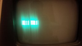
As a test, I just tried to load a little "Hello World!" looping program from cassette? No problem. The cassette stopped when the program finished loading. When I ran it I saw this:

Hello World.jpg

Seems to be working great except for the video.
 
In addition to the above, it looks like I am only getting one line of the 7 or 8 pixel lines of the characters when I type. What I found odd was that if I typed the 2 key, I could be getting the highest line of pixels in the number 2 (I can't really tell) but if I went to the next line by hitting return, I would only get a dot or two when typing 2. Maybe that was the second highest line of pixels. Next line with the same key was a different pattern of dots (maybe the next line of pixels or a single dot). Oddly enough, the above example looks like well formed characters but I think it's showing one line of pixels in an alternate fashion from each letter on each of the 24 lines (that makes up an inch or so). If there are seven lines of pixels per character, it's showing one line of each "Hello World!" then the next line of pixel on the next line and so on until you see 24 lines of single row pixels. I hope I'm describing this correctly.

Maybe it's a character generator chip? Just a theory.
 
If the problem is vertical, it's not the character ROM. It's probably the glue logic around it.

Something appears to be wrong with the video hardware on the logic board. From what little I can see at this distance, unfortunately I can't narrow it down much better than that. You may well just have bad video RAM.

Do you have the schematics, and are you able to read them?

If I were you, I'd first socket and replace the video RAM, then build a breakout board for the character ROM, and work from there; but I'm not you. And, unless you have something to drive the circuitry, that doesn't help you much.

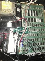
Here's my preferred way to diagnose PET video:
IMAG0106.jpgIMAG0107.jpg
Hardly ideal, but it sure works.
 
...Maybe it's a character generator chip? Just a theory.
Not likely; you're not putting characters where they're supposed to be, so it doesn't matter what the characters are.

If you crank the brightness pot all the way up, do you see a full screen (blank, except for your garbled text line) with diagonal lines?

Do you have a 'scope?
 
You may well just have bad video RAM. If I were you, I'd first socket and replace the video RAM, then build a breakout board for the character ROM, and work from there; but I'm not you. And, unless you have something to drive the circuitry, that doesn't help you much.

I haven't yet done one of the first things you should do when troubleshooting. I haven't reseated the socketted chips. Those irreplaceable ROM and RAM chips have me a little worried on this one but that's what I'm going to do next. Yesterday I eliminated the monitor but I didn't have time to reseat the chips. Today I'll reseat everything and see what develops.

If you crank the brightness pot all the way up, do you see a full screen (blank, except for your garbled text line) with diagonal lines?

I did that this morning before heading to work. It's very difficult to tell on this monitor but after inspecting closely, I'm pretty sure it's only the one inch that is located where the Hello World! example text is as noted in the pic above.

dave_m said:
If you have a scope or frequency counter, you might check the Vertical Drive signal for 60 Hz.

I'm guessing vertical drive would affect the screen height? This sounds like a good possibility but I don't know how to check for vertical drive.

I do have a scope but I confess that I don't know how to use it yet. In diagnosing a KIM-1, where I thought I was supposed to get a square wave, I was seeing a sine wave so I put that on hold until I could learn how to use it properly. Haven't had the chance yet to figure it out.

I also have the schematics and can use them to locate ICs, check continuity and check noted voltages but that's the limit of my knowledge.

I do appreciate everyone's help. Tonight I'll reseat the chips and see if that makes a difference.
 
While you're at it you could try replacing the 6522 and the 6520 at G8 with known good ones from the other board, but it kinda looks like the problem might be somewhere in that B6/C6/D8 area at the top middle of sheet 3. If you can have both PETs running at the same time you could use the scope to compare the various signals in that area.
 
I'm guessing vertical drive would affect the screen height? This sounds like a good possibility but I don't know how to check for vertical drive.

I do have a scope but I confess that I don't know how to use it yet. In diagnosing a KIM-1, where I thought I was supposed to get a square wave, I was seeing a sine wave so I put that on hold until I could learn how to use it properly. Haven't had the chance yet to figure it out.

The Vertical Drive signal is a standard +5V signal located at chip D8-pin11 on sheet 3 of the 320008 assembly schematic. At the top right of sheet 3, you can also see it is at connector J7- pin3. J7 is the signal connector that goes to the monitor. Note that J7-pin6 is missing and is used to properly orient the connector. The waveform is a skinny negative going pulse of about 2 mS and the pulse period is about 16.6 mS (60Hz). With power off, remove the J7 and hook the scope to pin 3 on the board. Power up and check the waveform. The monitor of course will be dark. You may see a dot for a second in the middle of the screen. When finished, power off and properly reconnect the J7 connector. Before removing any connector, it may be good to take a photo of the connector mated on on the board or mark pin 1 to make sure you reconnect properly.

As for the sine wave, you should be using a scope with a bandwidth of at least 5 MHz and usually about 40 MHz and use a standard 10X probe (attenuation of 10) to see a good square wave on a 1 MHz clock. Or are you using one of the USB digital sampling gadgets that hook up to a computer? In that case the sampling rate is probably not good enough to properly see high frequency signals.
-Dave
 
While you're at it you could try replacing the 6522 and the 6520 at G8 with known good ones from the other board, but it kinda looks like the problem might be somewhere in that B6/C6/D8 area at the top middle of sheet 3. If you can have both PETs running at the same time you could use the scope to compare the various signals in that area.

Hi Mike,
Right, hopefully the problem is just the generation of the Vertical timing signal and not in the screen refresh logic timing which can be messy.
-Dave
 
Back
Top