• Please review our updated Terms and Rules here

PET 2001-8 Swap similar motherboards for testing?

Hi Mike,
Right, hopefully the problem is just the generation of the Vertical timing signal and not in the screen refresh logic timing which can be messy.
-Dave
Amen! I've got one that duplicates the first character (top left) about half way down the screen; really must look at that some day... ;-)
 
Yesterday I didn't have a lot of time but I did manage to re-seat all of the socketed chips and put it back in its original PET. That didn't help as I saw the same thing. After a good cleaning, my keyboard now works but I tried to load the "Hello World" program on this PET and the cassette didn't stop. Fast forward and rewind also don't work of the cassette is in it but do if the cassette is not there. The cassette tape is not tight at all. This is just a symptom I figured I'd mention.

I didn't check what dave_m suggested yet. I have a Tektronics 465b scope so I should be okay but there's a lot of buttons and dials and is a little intimidating for a newbie. I'll try to give it a shot tonight or tomorrow.
 
Fast forward and rewind also don't work of the cassette is in it but do if the cassette is not there. The cassette tape is not tight at all. This is just a symptom I figured I'd mention.
Sounds like you need to replace the belt; is this the original white key drive or the later black key?
 
What you're experiencing may be normal. A datasette connected to my C64 does exactly what you describe, and I always wondered why. PETs do not do that, from what I've seen, but maybe yours is like my C64 for some reason.
 
Fast forward and rewind also don't work of the cassette is in it but do if the cassette is not there. The cassette tape is not tight at all. This is just a symptom I figured I'd mention.

Mike is right, replace the belt. The PET does not control the FF or REW buttons. It only switches +9V power to the cassette motor.

I didn't check what dave_m suggested yet. I have a Tektronics 465b scope so I should be okay but there's a lot of buttons and dials and is a little intimidating for a newbie. I'll try to give it a shot tonight or tomorrow.

Tektronix 465B, wow, I'll say you are in good shape. I wish I had one. I use a 453, an early predecessor to the 465. The 465 is small and bullet proof. Army tanks should be made so rugged. We can help with tips on the using the scope. Please tell me you have a set of probes. We'll let you know how to 'compensate' them for capacitance loading to get accurate square waves. There is usually a screw adjust on the side.
 
Last edited:
The Vertical Drive signal is a standard +5V signal located at chip D8-pin11 on sheet 3 of the 320008 assembly schematic. At the top right of sheet 3, you can also see it is at connector J7- pin3. J7 is the signal connector that goes to the monitor. Note that J7-pin6 is missing and is used to properly orient the connector. The waveform is a skinny negative going pulse of about 2 mS and the pulse period is about 16.6 mS (60Hz). With power off, remove the J7 and hook the scope to pin 3 on the board. Power up and check the waveform. The monitor of course will be dark. You may see a dot for a second in the middle of the screen. When finished, power off and properly reconnect the J7 connector. Before removing any connector, it may be good to take a photo of the connector mated on on the board or mark pin 1 to make sure you reconnect properly.

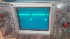
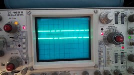
On J7 Pin 3 I'm getting 4.28 volts which seems kinda low but just for clarification, I have tried a good board with this power supply and it was fine. I also see this on the scope.

unnamed.jpg

To me it looks like it's around 4 volts (volts/division is 2), drops down to 0 for .25 milliseconds then resumes for about 2.25 milliseconds? (time/division is .5ms). I could be reading this wrong so I provided the image.

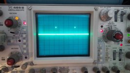
EDIT: I did the same thing to my working PET 2001-8 and the voltage was at 4 volts measured and with the same settings, I did not see the same thing. I did see the 16ms delay and probably a drop for about 2ms like you mentioned when I readjusted the time/division to 5ms (as opposed to .5). I also saw a straight wave not like the tiny pulses on the top of the 4 volt square wave like the picture. Since my my connectors were different on this PET, I ws able to do it with video still plugged in (if it makes a difference).

As always, much appreciated.
 
Last edited:
To me it looks like it's around 4 volts (volts/division is 2), drops down to 0 for .25 milliseconds then resumes for about 2.25 milliseconds? (time/division is .5ms). I could be reading this wrong so I provided the image.

OK, that would cause the 'vertically impaired' display you are getting. That is real progress. The 4 Volts is fine, anything above 3.2 V is OK.

Be patient, we will have to trace back and look at signals from the jungle of flip flops and other chips to see where the problem creeps in. It could be the JK flip flop B6 or perhaps C7, but I don't think we will be that lucky.

The root of the problem may be a bad screen address decoder output at D8 pin 6. We may have to probe a lot of signals before we find the bad chip. In a later design, Commodore would scrape all that discrete logic and replace it with a 6545 CRT controller. However at least we can fix the problem by replacing a little 14 or 16 pin chip. We just have to find it. Hang in there. We need to think like Sherlock Holmes. Old MikeS will be of great help. He is called the bloodhound of Commodore Pets. With his help we will sniff it out.
-Dave
 
Thanks dave_m.

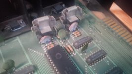
I was about to add one more pic. I do see a couple of ps that look a little crusty in the back corner nearest the transformer. I'm not sure if this makes a difference but I figured I'd post a pic anyway. Might these matter? The same two caps on my other PET look totally fine.

2001 caps.jpg
 
... We just have to find it. Hang in there. We need to think like Sherlock Holmes. Old MikeS will be of great help. He is called the bloodhound of Commodore Pets. With his help we will sniff it out.
-Dave
Oh no; I happily cede that title to you, Dave.

As I said, it might make it a lot easier if you could have both PETs running side by side with grounds connected, and compare scope readings in the suspicious areas.
 
Thanks dave_m.

I was about to add one more pic. I do see a couple of ps that look a little crusty in the back corner nearest the transformer. I'm not sure if this makes a difference but I figured I'd post a pic anyway. Might these matter? The same two caps on my other PET look totally fine.

View attachment 20032
I wouldn't worry; just looks like a little mildew on caps on the cassette drivers; should just wash off with a damp toothbrush.
 
Oh no; I happily cede that title to you, Dave.

OK, Mike, enough said, I will quit making up titles for you! ;)

As I said, it might make it a lot easier if you could have both PETs running side by side with grounds connected, and compare scope readings in the suspicious areas.

That is quite an offer which might quickly fix the PET. As you know the feedback nature of that video controller makes it difficult to find the bad chip as so many signals will look bad. I wonder if the OP can attend the next Toronto PET Users Group?
 
OK, Mike, enough said, I will quit making up titles for you! ;)
Just sayin' that IMO you're the PET guru here, especially the most active and most often helpful!

That is quite an offer which might quickly fix the PET. As you know the feedback nature of that video controller makes it difficult to find the bad chip as so many signals will look bad. I wonder if the OP can attend the next Toronto PET Users Group?
I've invited him a couple of times; we'll see. There are also at least a couple of local PET folks whom he could visit or vice versa, but I think he actually has a second working PET himself; AFAIK there's little or no relevant difference in the video circuitry between the -008 and the -137 boards.
 
Thanks for the replies guys. I actually like to try to figure stuff like this out. I'm just not yet sure how to use a scope or what to look for. Here's what I was trying today to to try to troubleshoot with a scope and two PETs (one working, one not).

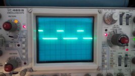
First I calibrate with the working PET and then check the bad screen output PET. Starting from J7 pin 3 on the schematic I've been using the scope to check for a similar wave between the two units. I then moved backwards so the next item was D8 pins 11, 12, 13. I checked both PETs and the signals are not the same. So I went back to the next chip which is B6. 5 volts is fine on pin 10 and 13 but scope output on pin 2 and 11 is not the same on both PETs. So onto C6...

So I am basically working backwards until I get the same signal. If I ever find the same scope output, then I am guessing that the previous chip I checked is no good. Does this make sense or am I going about this wrong?

Thanks guys for the pointers.
 
So I am basically working backwards until I get the same signal. If I ever find the same scope output, then I am guessing that the previous chip I checked is no good. Does this make sense or am I going about this wrong?

No, this will find the problem eventually. But the problem is that the Q outputs of the B6 Flip Flops, that you are starting with, are the outputs of a sequencer. The State table is shown next to the flip flops. It sequences from state 00 (Vert Drive) to state 01 (Top Blank) then state 11 (Video On) then state 10 (Bottom Blank) and then back to the beginning state 00. All this should take 16.66 mS. Everything will look wrong there. The waveform timing is wrong because the gated clocks are arriving too soon at the B6 flip flops. The clock derives from the count decoder at the bottom of the schematic at D8-pin6. The question is what is the bad chip in the maze of counters, latches and gates in the middle of the schematic that is causing the incorrect timing. I would start at D8-pin6 and work back from there. I suspect that the problem is with the D8-pin3 chain of signals as that gate decodes the long count.


Be patient and you will find the problem. Take photos of the scope displays so we can all have fun helping with the detective work.
 
Last edited:
I understand what you are saying but I just don't know exactly what to check and what I should expect to see. I would assume that at some point, the two PET scope outputs would be the same but I've checked a few points and none of them seem to match between the two. Could the different revs make a difference?

I really like this schematic with scope outputs at various points and wish there was one for the PET 2001 portion of the schematic I'm trying to diagnose:
http://www.zimmers.net/anonftp/pub/cbm/schematics/computers/pet/2001/video-1.gif

I'm not sure if this will help but could you tell me the points in the schematic I can check and I'll produce something like this for both PETs? Maybe that would help me and others who find this thread later on.

One other question. It looks like we are circling around 4 or 5 ICs here. If I should happen to have one of these, can they be piggy-backed on to try it out? It may be a stupid question but I fixed an Osborne Vixen video problem this way and it would save me from removing chips that are fine.

I appreciate the help, as always.
 
I would assume that at some point, the two PET scope outputs would be the same but I've checked a few points and none of them seem to match between the two. Could the different revs make a difference?

Not in this circuit, as Mike mentioned, all 1st generation PETs use this circuit; I assume you are looking at the schematic sheet 3 for the 320008 assembly with old style ROMs and RAMs (6540 & 6550)? The problem is that when there is a problem (bad output), a lot of the signals will look bad due to the feedback nature of the circuit.


I'm not sure if this will help but could you tell me the points in the schematic I can check and I'll produce something like this for both PETs? Maybe that would help me and others who find this thread later on.
Yes, I would like to see the following points: D8-pin1, E8-pins 4,5,2 and 1 and finally D8-2. They are all at the bottom of the schematic.

One other question. It looks like we are circling around 4 or 5 ICs here. If I should happen to have one of these, can they be piggy-backed on to try it out? It may be a stupid question but I fixed an Osborne Vixen video problem this way and it would save me from removing chips that are fine.

That would be good to try, but remember if an output is stuck low then the piggyback chip might not be able to force it high. You would be looking for any signs of improvement (change) not necessarily a fixed circuit.
 
Back
Top