• Please review our updated Terms and Rules here

Model II Graphics Card 26-4104

NF6X

Veteran Member
Joined
Sep 9, 2013
Messages
1,569
Location
Riverside, CA, USA
I'd like to learn about graphics card 26-4104 for the TRS-80 Model II and its descendants. Recently, a small handful of apparently NOS cards have appeared on eBay, and I bought one on a whim. At this moment, ebay seller rpsi92 has six more of them listed. These cards don't come with any software, cables or instructions.

I should be able to take pictures to share here this weekend, but right now it's late, and I'm about to hit the sack. The card has a 24 pin header and a 40 pin header on the edge, each with an adjacent empty DIP socket with the same pin count. Thus, I'm guessing that installing the card involves relocating two ICs from the original video card to the new graphics card, then connecting the new graphics card to the freshly vacated sockets on the video card with ribbon cables. Did I guess correctly?

I'm not sure whether I'd like to put this card in my Model II or my (not yet working) Model 6000. The latter would require pulling out one of the existing cards, since its cage is already packed full. My Model 12 doesn't have a card cage. I considered getting two of these video cards so I could stick one each in my II and 6000, but I decided to save the bucks and leave one more card out there for somebody else.

So, I'd like to learn about this card that I blindly bought, and this is a fine thread for any related discussion. Anybody else who has grabbed one of these cards recently is quite welcome to check in here.

I have many questions. Will it work in either my II or 6000? What software is necessary, and can anybody here provide it? Does installing it break any programs? How do I cable it up? Is it supported by any Xenix software that I might get my hands on? Would it make more sense for it to live in my II or my 6000? Will mankind walk on Mars in my lifetime? Why are puppies just so darned cute?

[yawn] Well, goodnight, y'all! I wonder if any of those cards on eBay will be left by the time I wake up tomorrow? ;)
 
These cards don't come with any software, cables or instructions.

I should be able to take pictures to share here this weekend, but right now it's late, and I'm about to hit the sack. The card has a 24 pin header and a 40 pin header on the edge, each with an adjacent empty DIP socket with the same pin count. Thus, I'm guessing that installing the card involves relocating two ICs from the original video card to the new graphics card, then connecting the new graphics card to the freshly vacated sockets on the video card with ribbon cables. Did I guess correctly?

I'm not sure whether I'd like to put this card in my Model II or my (not yet working) Model 6000. The latter would require pulling out one of the existing cards, since its cage is already packed full. My Model 12 doesn't have a card cage. I considered getting two of these video cards so I could stick one each in my II and 6000, but I decided to save the bucks and leave one more card out there for somebody else.

So, I'd like to learn about this card that I blindly bought, and this is a fine thread for any related discussion. Anybody else who has grabbed one of these cards recently is quite welcome to check in here.

I have many questions. Will it work in either my II or 6000? What software is necessary, and can anybody here provide it? Does installing it break any programs? How do I cable it up? Is it supported by any Xenix software that I might get my hands on? Would it make more sense for it to live in my II or my 6000? Will mankind walk on Mars in my lifetime? Why are puppies just so darned cute?

[yawn] Well, goodnight, y'all! I wonder if any of those cards on eBay will be left by the time I wake up tomorrow? ;)


I do have this card too.
I have no luck using it sofar.
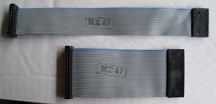
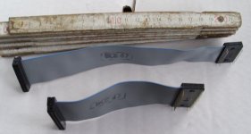
There is no hardware intallation guide with it, but I have two flatcables in the set.
You have to take out the 2 largest chips from your video board and put them in the graphics card.
Take a good look at the orientation of the chips. Connect both empty IC sockets on the videoboard with the two connectors
on the graphics card.

I did it with the following results. The computer boots normal. The screen resets and there are no characters on the screen just the
background is visable. If I blind type the commands the computer boots on.
I can see the location of the cursor and can see the movings of the cursor, thats all.
Il looks the the char generator doesn't work or is not connected in the right way.
I have my doubts about the orientation of the flatcable or moved chips.
After replacing the chips and boards there was no damage on my computer.
 
I've also been interested in the Model II graphics card for awhile now, and I also purchased from the same lot on eBay. I was also disappointed not to get the software and cables so I would love to find either of those as well. At least a pin out of the cables would be helpful. Hans? :)

Here is my understanding after a bit of research. The card provided 640x240 single color resolution. The card will work in any iteration of the Model II line. It requires its own special software utilities that are provided on the installation disk for Basic, Fortran, COBOL and assembly language. It will only work under TRSDOS 2.0 for Model II. There was no software published to take advantage of the card.

My interests are in developing software for the Model II so I'd certainly like to take advantage of the graphical capabilities supplied by the card. Unfortunately, if I do, then very few people will be able to use the software given the rarity of the card. Nevertheless, the software engineer in me salivates at the option. :)
 
I've also been interested in the Model II graphics card for awhile now, and I also purchased from the same lot on eBay. I was also disappointed not to get the software and cables so I would love to find either of those as well. At least a pin out of the cables would be helpful. Hans? :)


@pski.

Please take a look at this thread about the Model II http://www.vintage-computer.com/vcforum/showthread.php?46111-Tandy-stuff
In one of the last items are 5 pictures of the graphics card and showing the flatcables very wel.
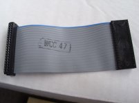
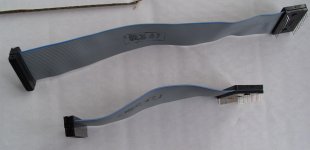
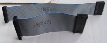
The flatcables are just as they shown. There are no orientation points or numbers on it.
The lengths, including the connectors are: 128 mm. and 216 mm. The number of wires are 24 and 40, as shown.

As far as I can remember, I have seen a picture of a Model II with the graphics card installed. The blue wires were faced downwards.

But as I told, there are no characters shown, only the background colors.
There are no jumpers on the board. It seems to me that printed mask for the orientation for one of the moved chips is wrong.
But I have not had time to seriously check this.
 
@pski.
The flatcables are just as they shown. There are no orientation points or numbers on it.

@Hans01, do you suspect that the ribbon cable matches the IC pins number for number exactly?
 
@pski

The IC replacement connectors on the flatcable are put in the sockets 1 to 1. As the only direction they can insert in the board,
the pins are 1 to 1 equivalent with the IC's.

The connectors for the graphics bord can be inserted in 4 way's. Flatcable coming from left or from right and the blue wire on top side or
bottom side.

The short one can, accordingly the length only inserted with the blue wire downside. Left and right is possible.

As the first four cards in the card bay has their own position, the graphics board can only be placed at pos. 5 or higher, the short cable
has then only one option.

As there are no characters shown, there could be a problem with the small IC (Character generator).
So it is possible that the mask on the PCB could be turned around 180 degrees. I have not had time to check it.
Just don't insert the chip or flatcable turned around only after being very shure !!!!!!
 
These boards require a couple of changes to install. I have attached the section from notejump.pdf and the technical bulletin it refers to.

Here is the jumper settings for the Model II hires board. I have attached the technical note as a Zip. I'm also looking through my Tandy Faxback download to see if there is anything in there.
MII-HiRes.PNG

I just checked the faxvback archive. Here is what they say:
Code:
TANDY  HI-RES GRAPHICS UPGRADE  (260-4104)    Faxback Doc. # 2138
___________________________________________________________________________

*For use with Model II/16

----------------------------------------------------

There are hardware modifications for this board- I/O:041, I/O:050

64K memory minimum
640 X 240 byte addressable pixels
Installation by Radio Shack Service Center
* Not for use with Xenix
Anyone have a source for the I/O technical bulletins? I have the Model II, Model 16, Model 6000 and Hard Drive tech bulletins as PDFs. I don't see the I/O ones anywhere. I also checked further in the the II tech bulletins. Order of card placement may also be important. It is explicitly specified for every type of the model II family.
 

Attachments

  • MII-TechBulletins.zip
    60.7 KB · Views: 7
Last edited:
@kb2syd.

Thank you very much for the info.

Can you help us with the way to connect the flatcables and the order of the graphics bord in the cage of a model II

Thank you in advance.
 
Model II Board order

The recommended order for boards to be installed intot the Model II card cage starting at the side nearest the power supply is:
Code:
Z-80 CPU Board  -- REQUIRED
FDC Board       -- REQUIRED
ARCNET board                     --(if installed)
Hard Disk interface board        --(if installed)
Disk Cartridge interface board   --(if installed)
Multi-terminal board             --(if installed)
Z-80 memory board(s)
KB/Video board 
  graphics board next to it      --(if installed)
68000 CPU and memory boards(s)   --(if installed)

The Z-80 CPU board should be installed in the first slot (nearest the power supply). The other boards should be installed with no empty slots between them so that the interrupt system will work properly. The only exceptions are the 68000 boards, this is because the do not use the Z-80 interrupts. To make installation easier, the 68000 boards can be installed into the slots furthest from the Z-80 CPU but make sure that the foil side of the board does not short out against the side of the card cage.

When more than 5 Z-80 board are installed into Model II the power supply will have to be upgraded to and AXX6008 or an AXX-6009 type, and a new 5 volt supply wire must be routed to the mother board (AW-2841). With the AXX-6008 power supply, it will be necessary to adjust the power supply output voltage every time the number of boards is changed. Refer to Technical Bulletin II:29 for the ZXX-6008 power supply adjustment procedures. If any 68000 boards are used a AXX-6009 power supply must be used.

The cables for the video board jump the chip sockets over to the existing video board. You remove the IC from the original video board, install them in the Hi-Res board then plug the jumper wires into the open socket. The should be 1 for 1 from board to board. You can verify this by tracing the leads from the sockets to the cables.
 
The "* Not for use with Xenix" note tells me that this card will go in my Model II. Thanks! Now, to study the tech bulletins while I drink my morning coffee...
 
Hmm, interesting! I think it'll still go in my II, since it has 4 slots free and my 6000 is packed full. I'd need to remove either a serial port card or the Bernoulli card (don't have a drive for it yet...). Who can live with just 5 serial ports? :)
 
The manual you guys are looking for is titled:
TRS-80 Model II Computer Graphics Manual

I think I have a copy. I'll look this weekend. It is not a big manual.

It is also in the collection at http://mediaarchaeologylab.com/catalogue/printed-matter/manuals/ but I don't see any way to actually get it from there.

I'll still can't print any ascii character on the screen.
I have done the CPU DMA patch without any result.
During boot the 'TC' logo is shown. which is in inverted graphics ascii characters. The position of the cursor is shown on the right
location and I can type commands which are executed,
but there is no echo on the screen. The background of inverted text is shown as a black square with the size of the text.
The dipswitches are in the right positions ( 1,0,0,0 )

Anybody an idea ?
 
I have one or two setups here from a very early CAD system. I'll open it up in the next couple of days and document the switch and jumper settings on all cards. Please remind me by PM if I don't get back to this in a day or two.
 
I've acquired a card, a donation from a good buddy of mine, can anyone advise me how to build the cables?

Or even better, if I could just pay someone to make me a set, I'd be happy to pay for the peoples expertise in that area.

It will allow me to continue my studies into hi-res TRS-80s.

Cheers,

Ian.
 
There are two cables needed that go from card edge to dip. I don't remember the pin count, but they are 1-to-1 cables. They are about 10 inches (25 cm) long.
One end is card edge crimp on like: http://www.ebay.com/itm/Card-Edge-3...932?pt=LH_DefaultDomain_0&hash=item43da8b1d54
The other is crimp on DIP like:http://www.jameco.com/1/1/25575-8200-28-connector-idc-dip-plug-28pin-1a-use-37840.html

Of course these are just samples of what you need, not the exact items. You then remove the corresponding ICs, move them to the graphics card and plug the jumper cables in between. I still have to get to one of the units I have that came with graphics installed.

Edit: Forget the card edge part. I see they are simple row header ends.
 
Last edited:
I've acquired a card, a donation from a good buddy of mine, can anyone advise me how to build the cables?
Ian.

Hi Ian, the disks you sent me have just arrived. Thank you very much for it.
For the Model II harddisk I can tell you that James is still busy drawing the PCB. As soon as I have more news I'll come back with more information.
I work with the harddisk for a week now, without any error or problem, it's great.

The graphics board for the Model II gives me more problems.
I didn't have any succes with it. I can put it in the computer and the computer keeps working but there is no text on the screen.
I can see the cursor and if I type it is moving. I can see the background and the inverse parts, but there is no visable text.

I think it has to do with the chips you have to replace. It looks like the character generator's orientation is wrong.
According the marking on the PCB the character generator must rotate 180 degrees. (I have my doubts)
According the length of the small cable there could be made a twist in it.
There is nothing in the manual about the installation of the hardware.

For the moment I can help you with a set of pictures of the cables. I think you can easily build them with this info.
I don't have these connectors for you. It very difficult to buy them in Holland.

I hope you have more luck with the graphics board.

HPIM0230.jpg HPIM0234.jpg HPIM0231.jpg HPIM0232.jpg HPIM0233.jpg
 
I think it has to do with the chips you have to replace. It looks like the character generator's orientation is wrong.
According the marking on the PCB the character generator must rotate 180 degrees. (I have my doubts)
According the length of the small cable there could be made a twist in it.
There is nothing in the manual about the installation of the hardware.
One way to tell if the silk screening is wrong is to check the vcc and ground lines for continuity. Pin 1 should still map to pin 1 electrically.
 
Back
Top