• Please review our updated Terms and Rules here
  • From now on we will require that a prefix is set for any items in the sales area. We have created regions and locations for this. We also require that you select a delivery option before posting your listing. This will hopefully help us streamline the things that get listed for sales here and help local people better advertise their items, especially for local only sales. New sales rules are also coming, so stay tuned.

Vintage 1995 Pionex 486 DX2 66 Mhz Computer

Alright FDISK first then FORMAT, all through command prompt. I'll try the FDISK /mbr thing first though since a version of DOS is present on the hard drive as well as Windows, just in case.
 
I'm using a ps/2 to 5-pin din keyboard adapter and for whatever reason sometimes one key results in two letters being inputted. I tried typing fdisk /mbr but when I type "m" it puts "hm". Can I move the cursor to delete the letter h with the keyboard so the command can work or would I have to have a mouse? Arrow keys just delete the letters like backspace. "fdisk" by itself types and opens fine.
 
Try insert then move back. Or have the capslock in the other position. Dos doesn't care whether it's upper or lower case.
Sounds like the keyboard is faulty and could be causing other issues. Got a spare? This'll rule out the mobo keyboard bios.
 
Last edited:
Alright, fortunately for me my Microsoft PS/2 keyboard I got today works perfectly with the adapter. I did the fdisk /mbr and rebooted my computer without the Windows 95 boot disk and it started loading Windows 95 off the hard drive. I chose start normally and got this message :

"Cannot find a device file that may be needed to run Windows or a Windows application. The Windows registry or SYSTEM.INI file refers to this device file, but the device file no longer exists. ....... "try reinstalling that application to replace the existing file.

d:\PROGRA~1\NORTON~1\NAVAP.VXD"

I clicked a key to continue an it booted into what I assume is Windows 95 Safe mode. Background has purple diagonal lines. Got a "cannot find the file 'far_Inch.exe [or one of its components] in the WIN.INI file message upon everything loading. Then says it can't read from drive D. Lastly a status monitor window popped up and stated its status as "setting COM port". Without a mouse that's as far as I got.
 
Sweet. You can have a poke around with the keyboard using arrow and tab keys. You open notepad and edit the win.ini and system.ini files to remove the entries it moans about.

Anyway at least you know the hdd boots ok. Probably the original Windows 95/Upgrade on Fat16 file system.
 
Last edited:
Yeah, funny it just needed a new battery and master boot reset. I bought a tested VESA video card and ISA POST card since the display wasn't working originally, 5-pin din keyboard adapter since I don't have a din keyboard, Windows 95 boot disk and installation disk with product key, and lastly a new CD-ROM drive since the proprietary Sony driver wasn't being detected. Barely needed anything to actually get it to boot after all, but have some useful parts now I can use for future vintage computers.

Not seeing how I can do much with the keyboard on the home page with just the keyboard. Pressing enter keeps it cycling through the couple of errors/things it wants to to fix.
 
At least you stuck with ;). You'll probably find the D: drive error is relating to that Sony CDom or maybe just some stuff that was on the Cav. drive. Wouldn't be surprised if you hooked it up and that error disappears. Not that it matters now when you do a clean install from the IDE cdrom.
 
Last edited:
Yeah I thought the same about the Sony drive when SCANDISK said the hard drive was fine. The Hitachi will be just another part to hold onto in case I need it later. Thanks for your help!
 
No problem at at all. After all that is what vcf is all about.

Some malware may have hosed the mbr rendering the system apparently unusable. Wouldn't be the first time this has happened.
Had the partition table waxed on a Win2k box a couple of weeks ago.
 
Last edited:
Alright so I tried hooking back the Sony CDU31A CD-ROM that came with the PC and when I turned it on the computer gave a HDD controller failure error and wouldn't boot. This CD-ROM is proprietary and was connected to the sound card via a 34-pin IDE cable along with an audio out cable. With the Hitachi drive it boots to Windows 95, however, it is slaved to the HDD and I don't have an audio out cable that will fit the connection on the sound card now. The sound card audio and Hitachi CD-ROM audio connections are different sizes, so I guess I'd need a different sound card. Additionally, upon bootup I get a message saying drive d: will not work and also that the sound will not work.

One other minor issue is that the turbo LED is always on whether or not it is depressed or not. Also, I read one case where the LED display changes from 66 to 33 when turbo is on since the speed slows down with turbo, but the speed is always shown as 66. A few times it would turn off when I depressed it and back on when pressed again but that didn't last long.
 
Last edited:
I have that exact same Pionex computer I got non-working off of EBay. Re-seated a few cards and it fired up. Clock battery is dead as well though. I have the same issue as you with the LED display -- it's the most confusing one I've ever seen, seems to have pins for both of the switching designs found here, and I can't find a diagram of it anywhere. My Turbo LED stays lit all the time as well, and pressing the button does nothing to change the speed display from 66. I don't suppose your came with a diagram somewhere for that display?
 
Glad to hear yours fired up with little work, it took me a while before I could even get mine to post. Replacing the RTC battery was all it needed for that, boots to Windows 95 now. Just have to get and install the NOS sound card I ordered and I'll sell it.

Regarding the turbo button though I fixed it. The yellow/black cable was not on the right pins. LED is on when not pressed and off when depressed now, but the speed display still remains 66 on either setting. I read on another forum most of these displays didn't actually have the number change so I think it's fine. I don't have a diagram, but I have posted a picture of where I have the yellow/black cable connected now. If you happen to get the display to change from 66 to 33 please be sure to let me know what connections to change.

On another note, if your motherboard is also the same as mine it should have a rectangular 12887A RTC battery. I got a brand new one from China here:

http://www.ebay.com/itm/281569710514?_trksid=p2057872.m2749.l2649&ssPageName=STRK:MEBIDX:IT
 

Attachments

  • Display.jpg
    Display.jpg
    84.5 KB · Views: 2
Last edited:
Thanks! I think I can swing a few bucks to replace that battery. If you don't mind taking the time I would love to get a pic of how your LED display is wired.
This is one really awesome case; I have fond memories of Pionex from high school and am attempting to revisit a bit of that.
 
The picture I uploaded is of the LED wiring as well as the connections to the 66 mhz display circuit board. The only LED wiring not visible is the HDD one. Yellow/black goes to the LED in the background as well as the spot on the front panel board, green/black goes to the power LED. The yellow and black cords on the front panel are what I moved to fix the turbo LED always being on. I hadn't heard of Pionex before I saw this computer, but I got it primarily because it looked like a good machine in a neat case.
 
Last edited:
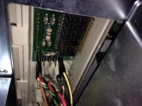
Wow, that is crazy, I can't even get my display to turn on pinned like that. Not sure how yours is working...on the top left row, the last two pins labeled "5V and G," I believe is supposed to be for the power cable. Yours has the red wire going to 5V, which makes sense, but the black going to the ground on the left, which according to the brackets on the circuit board looks like its intended to be for the ground for the signal wire coming from the motherboard's turbo LED (there is no ground wire for that, however, not needed). My display won't turn on if I wire it like yours. But hey, if it works, don't mess with it.
And the turbo light won't come on in mine wired like you have yours; however, it will come on and stay lit if I wire it to "+P" and "-P" (fourth row of pins down on the left). I can't get it to switch off though.
The turbo switch is functioning, but I still can't get the display to change. It's weird though -- I run MAXSPEED with turbo on and it says it's going at 64mhz. Turn if off and it only clocks down to around 52. I haven't tried any other programs to see if they say something different.
Funny thing is, when I first got the machine, pressing turbo would change the display from 66 to some nonsensical number, but not consistently. However, now after messing around I can't get it to change at all, even going back to the way it was. I've tried every possible jumper combination, but there only appears to be one jumper setting (vertical, every other jumper shorted) that causes an LED segment to light. The first two rows are for the 3rd digit (the ones), the second two rows for the middle digit (the tens) and the third two rows for the first digit (the hundreds). On yours, no pins on the last two rows are jumpered (because your display is just 66, no first digit). Mine is jumpered to display 066. But for the life of me I cannot get it to change when turbo is pressed.

Sorry for the rambling post. This thing has bugged me for days whenever I get a chance to mess with it. I know it's not really important, but I would like to solve the puzzle. But I'll just be content with 66 displaying all the time and the turbo button always being lit. If I want slower, I still have a 386!
 
Yeah, at one point I thought a bad power supply might have been an issue with it so I tried a different one and some of the front panel cables got disconnected when I was disassembling, so I'm not 100% they are where they originally were. If you could upload a pic of how your system was originally set up where you had the nonsensical number a couple times I could try that setup on my machine and see if it works for me. Perhaps some aspect of your front panel board has gone defective at some point resulting in the garbled number? I think how the display looks is determined by the jumpers though so I suppose some jumpers could be set incorrectly. I haven't moved any of my jumpers at all.

I was glad to fix the LED always being on, but it would be nice to have it set to change the speed as well if possible.
 
P1010047.jpgP1010048.jpg

Ok, but I'm not responsible for any ensuing madness / insanity this may cause. The jumpers looked like this when I got the machine. The wires did not (if they're working for you now I'd leave them), I have no idea how they were set up, but the turbo light didn't come on at all then.

Here's the thing. When I got the machine, the way the jumpers were, it said "066" and then changed to some weird number when I hit turbo. Now, set up like this, it displays what's in the second picture, and doesn't change when I hit turbo.

So now, if I want to set it to 066, I make the second row of jumpers (the tens digit) exactly like the first (the ones digit). Makes sense. How it was before didn't make sense, but for some reason it worked.

As mine is now, only the vertical jumpers cause any segments to light. The horizontal ones do nothing.

Good luck, hope you find something out!
 
Last edited:
The way those displays typically work is that you have a pin for each LED segment, and the jumper for each one can be set in one of four states. One state is to use the jumper to connect the LED straight to the power source. This leaves that segment on all the time, regardless of the state of the Turbo button. The next two states use the jumper to connect to one side or the other of the Turbo button. One of these pins will be connected to power when the Turbo button is pressed in, and the other will be connected to power when the Turbo button is not pressed in. This allows you to select segments that are only active when the Turbo button is in a specific state. The fourth state is to simply remove the jumper, which leaves the segment inactive regardless of the state of the Turbo button.

Typically they'll have an arrangement similar to this (two segments shown):

Code:
Always inactive:
 XXXX
XXXX

Always active:
 |X|X
X|X|

Both connected to Turbo State 1:
 X--X
--XX

Both connected to Turbo State 2:
 XX--
X--X

One connected to Turbo State 1, the other connected to Turbo State 2:
 XX--
--XX

That might be a little hard to visualize, but imagine each segment as a T-shaped group of pins (denoted by the 'X's) and you can set the jumper (denoted by -- or |) from the "middle" pin to any of three "outer" pins, or to none of the pins, to get the effect you want out of the display. Note that the pin arrangement isn't always consistent, but there should be silkscreen labels on the board (if the manufacturer was sensible) to help you out a bit. You can always use a multimeter to help you figure out which pins are which as well.
 
Back
Top