• Please review our updated Terms and Rules here

Model 4P Scrambled Video in 80 Column Mode

tempest

Veteran Member
Joined
Sep 16, 2014
Messages
930
Location
SE Michigan
I just got a non-gate array 4P and it appears to be working just fine in Model III mode and 40 column Model 4 mode. But when I try to load a DOS that uses the 80 column mode (LDOS 6.3.1. MULTIDOS 2.1, TRSDOS 6.2.1) the screen is scrambled. The seller told me that I might need to adjust the video display. I found something about adjusting a capacitor on the board on Ira's site:

If you happen to have the non-gate array mother board in your 4/4P and the video screen is “shakey” in the model 4 mode or speed and is NOT while in the model 3 mode, the video VCO (voltage controlled oscillator) which generates the 80 character by 26 line signal is probably on the edge of stability. This sometimes shows up more as the ‘puter warms up.
On the 4P: in the front of the board, between U148 and U149 there is a variable capacitor (usually orange in color) designated C231, but you probably can’t read the designation. It is about 3/8 inch in diameter, and has a whole in the top with what looks like a screw slot in the hole, you are looking at what is probably the culprit!! Using an insulated shaft TUNING tool that will fit into the hole, with the ‘puter in the model 4 and the ‘puter warmed up so the symptoms appear, adjust (just a WEE TAD) so the video is again stable. Do this gently or you’ll hate me!


Has anyone done this before? If so are there any tips you can share? Is there a video or picture showing where this capacitor is exactly? I assume I do this with the system off and keep adjusting it until it stops being scrambled.
 
Yes the varicap is in the hardest to reach, dumbest place right up the front of the motherboard.

I do it this way:

Open the system and undo all 8 screws holding the motherboard clamshell together
Set the system on its side (power switch/reset button/brightness contrast controls side)
Power it up and boot an 80 column operating system so you get scrambled video
Now carefully unplug the disk drive cable and swing the motherboard down while its still running
You can now easily reach C231 with a tuning tool and turn it only a couple of degrees either way until the screen stabilises.

Hope this helps,

Ian.
 
What kind of tool do I need to adjust the cap? I assume a metal screwdriver is right out of the question? Also anyone have a picture of C231?
 
Metal tools are not recommended as when you turn the screw on top you are in fact moving a ferrite slug within the varicap (or was that with a tuning transformer....) The metal shaft of the screwdriver can interfere with the antennuation and make it very frustrating to adjust. You need some sort of long plastic tool with a flat bladed end. I've seen someone make one out of a swizzle stick. ;)
 
Yes the varicap is in the hardest to reach, dumbest place right up the front of the motherboard.

I do it this way:

Open the system and undo all 8 screws holding the motherboard clamshell together
Set the system on its side (power switch/reset button/brightness contrast controls side)
Power it up and boot an 80 column operating system so you get scrambled video
Now carefully unplug the disk drive cable and swing the motherboard down while its still running
You can now easily reach C231 with a tuning tool and turn it only a couple of degrees either way until the screen stabilises.

Hope this helps,

Ian.

When you say "Swing the motherboard down", what do you mean exactly? Is the motherboard not held in by screws or anything?

BTW I found this site that has a nice tear down of the 4P. I can't see where C231 is though: http://www.techrepublic.com/pictures/cracking-open-the-radio-shack-trs-80-model-4p/
 
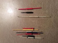
Image 21 top center looks like an orange variable capacitor described. If you don't have a small plastic screwdriver, you will need to whittle and make one or use a metal jeweler's type slotted screwdriver used for eye glasses. Using a metal screwdriver will tune the capacitance so you will need to turn slightly than remove it to check and repeat. I would wrap black tape around the handle to prevent your body from affecting the tuning. Here is a photo of my tuning tools used 100 years ago when I did service. The 3 set apart I used the most. The white one with the metal tip was the best for this type of adjustment:
tools.jpg
 
Last edited:
Image 21 top center looks like an orange variable capacitor described. If you don't have a small plastic screwdriver, you will need to whittle and make one or use a metal jeweler's type slotted screwdriver used for eye glasses. Using a metal screwdriver will tune the capacitance so you will need to turn slightly than remove it to check and repeat. I would wrap black tape around the handle to prevent your body from affecting the tuning. Here is a photo of my tuning tools used 100 years ago when I did service. The 3 set apart I used the most. The white one with the metal tip was the best for this type of adjustment:
View attachment 28466

I see it now. Now I just need to get to it. Does the motherboard on the 4P just 'slide out' when you take the back of the cage off or is it screwed down somewhere?

I have a jeweler screwdriver, will that work on its own? I also have electrical tape I can use to wrap it just in case.
 
BTW - I am not familiar with servicing TRS-80 series computers, just electronic service in general so others may have to step in for particulars. Yes, in the service manual p75, C231 is where that orange cap is in the picture. It adjusts a 12.6 MHz VCO. At that frequency, a metal screwdriver will influence the adjustment and definitely use black tape insulation. The only danger will be if the horizontal scan rate is influenced by this adjustment then the CRT display could be damaged if the frequency drifts too far. Is there a way to power off the CRT temporarily while doing the adjustment? That would be my only concern. Then a plastic driver would be best. Maybe just power off, tweak a couple degrees then power on. Of course, make note of the initial position of the cap. I used to just run a black marker across part of it for initial position.

Larry G
 
The motherboard tray is held, like I said, with 8 screws. They are 4 on each side of the tray.

The wires connectors for the power, video and reset button up the front of the motherboard are very short, very very short. So you kind of swing the whole tray downwards pivoted at the front while keeping these connectors plugged in and the system running, so that you have good access to the varicap.

Marking the varicap starting point is not going to be any use because the amount you need to turn it is only in the order of 2-3 degrees either way. As for overscanning the CRT, it can handle a couple seconds of it if you turn the varicap too far. Yet if you try to do it blindly with the computer or CRT switched off you may as well be playing darts.

Ian.


When you say "Swing the motherboard down", what do you mean exactly? Is the motherboard not held in by screws or anything?

BTW I found this site that has a nice tear down of the 4P. I can't see where C231 is though: http://www.techrepublic.com/pictures/cracking-open-the-radio-shack-trs-80-model-4p/
 
Ok I understand now. I'm a little nervous about pulling out the board while the system is running (I fried a TI-99 that way) but I think it's the only real way to do it. I have a chopstick package leftover from the last time I had chinese, I think I'll try and use that as a screwdriver. Any other tips or tricks I should know before attempting this?
 
I would still recommend visually marking it's original position, maybe just take a close up picture of it since it sounds like it's recessed in a hole so you can see the original angle of the slot. What might happen especially if you are using a piece of wood is the tool might mush instead of turning so then you look and try to decide did it turn or not? Been there, done that doing something similar before ...

Larry G
 
I was just about to take the 4P apart when I thought of something. If the capacitor only needs to be turned a degree or two (probably not even that since it was fine before shipping so it must have just barely rattled out of position), could I just turn it one direction with the power off and see if that fixes the problem? If not, turn it a degree or two the other direction and try that? If it only takes a tiny adjustment then I don't see a reason to risk adjust things with power on.
 
That was my thinking you might get lucky in two attempts. If you do get it to sync, then let it warm up maybe 30 minutes then power off / on and check if it is still in sync. What you are doing is adjusting the free run frequency of an oscillator to be within a certain temperature window that it can get locked. Or maybe accomplish the same test by switching resolution modes out and back in, whatever it takes to aggravate it. Test it cold and warm before you button it up.

Larry G
 
Fixed it! I got luck and did it without the system being on. I'll let it warm up for a few before I put it back together but I think I lucked out and did it on my first try.

Other than waiting for a bit to see if the picture shakes, is there anything else I should check before closing it up?
 
Back
Top