• Please review our updated Terms and Rules here

Old Pentium Project - AOpen AP5VM Mobo

It is actually not legal to use lead solder in most consumer electronics in the EU or US, however this doesn't apply to the home hobbyist OR to repair or electronics that pre-date this. There are certain exceptions; actually I thought automotive was one of them (and of course military).

I've found a lead-free that works well enough for me but it needs a lot of flux and effective fume extraction, and then a lot of cleaning to get rid of all that flux.
 
You want the "eutectic" (has no "mushy" phase--goes from liquid to solid directly) 63/37 alloy. It's called 60/40 in many catalogs, but isn't quite that.

You may be technically correct, but it's always been referred to as 60/40, at least in my circles. If you were to walk into an electronics supply outlet and ask for 63/37, you'd probably get a double-take.
 
AFAIK, for at least as long as I can remember Kester has always advertised its "44" solder as 63/37. To be sure, there are 60/40 solders and they're a bit plastic as they harden. Some people prefer this. If I'm soldering a radiator or tuba, I'll use 50/50 because I can "tool" the solder as it's hardening--and it also has good gap-filling characteristics.

Or maybe you're referring to the real old-timers--the ones who talk about "megacycles" and "condensers". I'm old enough to have done that myself, but learned early on to clean up my act. :)

On the other hand, I still use "mho" and not "Siemens". It just doesn't feel or sound right any other way.
 
Last edited:
...I still use "mho" and not "Siemens". It just doesn't feel or sound right any other way.

Yeah, never understood how a unit of conductance got named the same as a company I used to work for....

Back on-topic...as far as removing RAM, etc before working on the MoBo, if you're properly grounded (remember the thing about ESD), then in that respect you'd be ok to leave it in. Heat wise---stuff would have to be pretty close and/or pretty small (say SMT 0402 size or smaller) to be terribly concerned with normal soldering issues. If it's all THT (through-hole), then you'd have to get the pads pretty hot (to the point of burning them off) for other things to be affected. Again (and I know you're tired of hearing this), practice, practice, practice before working on something that seems to be of great value to you.
 
Last edited:
AFAIK, for at least as long as I can remember Kester has always advertised its "44" solder as 63/37. To be sure, there are 60/40 solders and they're a bit plastic as they harden. Some people prefer this. If I'm soldering a radiator or tuba, I'll use 50/50 because I can "tool" the solder as it's hardening--and it also has good gap-filling characteristics.

Or maybe you're referring to the real old-timers--the ones who talk about "megacycles" and "condensers". I'm old enough to have done that myself, but learned early on to clean up my act. :)

On the other hand, I still use "mho" and not "Siemens". It just doesn't feel or sound right any other way.

Old timers! that's got to be me. I even have a pocket knife that says 'Old Timer'. Every once in a while 60 cycles seems to pop forth. As far as lead goes, as long as you're not chewing on it or taking it directly in the chest, you ought to be okay.
 
Ok everyone, so today was the day!

I ended up going to that local electronics store so I could see what I was getting, and very glad I did. Helped me see what I was getting before I bought it, and also realized what I may forget if I was simply buying online
I bought the following:
  • that 25W soldering kit, including solder sucker, non Pb based solder
  • 60/40 solder - 1mm with core flux
  • solder suck wire (that's what is written) - guessing 2-3mm
  • wire pliers to cut the mesh.
  • helping hand stand
  • ic extraction tool
  • practice board
  • fat arse can of "flux cleaner"

So including the IC chip plus the 5 pack of sockets, I was good to go.

TLDR:
1st practice fail. See photos

image2 (1).jpg

image1new.jpg

Summary & Questions.

Fairly certain the solder is too thick. I should have known better. I didn't know what to say and asked the guy for "medium". Clearly "small" was what I needed. Given I was testing the socket on that board, the hole spacing is going to be similar, so every time I put the solder on the tip - it seems to dissolve on the tip and went to the side of the socket lead instead of in the hole (see picture).
So watching the videos, does't seem to match what I'm doing.
  1. Is it best to hold the solder on the opposite side where the solder tip is? Or put it on top of the solder tip?
  2. Should I change the orientation of the socket given it won't run to the side if the pad wasn't so large? (I'm guessing a big YES here)
  3. Solder sucker: is this IC too small for a solder sucker?
  4. Also - I wanted to hold the solder sucker in my dominant hand, and the soldering iron in the other. I was awkward. Is that the best way to do it?
  5. With the solder wick, seems I had to have the socket pin pierce the wick for it to be effective. Is there a better way, or was perhaps my solder wick too thick as well?
  6. Soldering iron tip cleaning. I was told to always leave solder on the tip (as you see in the photo) so it doesn't oxidize but it looks dirty like it did oxidize
  7. When I add a bit of solder to the tip, it only forms a ball on one side, how do I make it apply evenly. Turn it, use the sponge, other?
  8. Another way of asking it is, what is the combination of applying solder to the tip to get good thermal conductivity and using the sponge at the base?
  9. Is the 1 mm solder too thick for this work, or should I forget it?
  10. I accidentally inhaled one puff I think while in the moment... is this like radiation where a little won't kill ya, and should just be more careful or should I take measures to get a smoke sucker, face mask, etc
  11. Is the soldering tip too large?

Please feel free to critique, laugh, and more importantly any tips you can offer. I figure at this point I may practice again, but almost certain that with what I have right now - can't continue. (Added benefit - stores that would sell solder are not open on Sunday even during the 2x year "sales" period)

Thanks everybodee (aka old timers)! :)

Cheers!
 
Let me see if I can help out...

1. You don't really want to hold the solder on the tip--the flux in the solder works when the solder is melting--what's on your iron tip has no more flux. Make sure your tip is tinned (see your no. 6). I'd recommend a tip cleaner--they're inexpensive:

soldering_iron_tip_cleaner.jpg


Also, your work should be scrupulously cleaned of any dirt or corrosion. A bit of very fine (600 grit or better) emery paper will help. Most perfboard will have been sitting on the shelf for months and the copper will have acquired a thin layer of oxide. You want the copper to be bright and shiny.

Heat the joint to be soldered with the iron tip, then feed in solder to the heated joint. Allow the solder to flow a bit. Remove your iron from the joint and allow it to solidify--do not move components while the joint is solidifying.

1 mm solder is a bit thick, but will probably work well. Thinner solder requires less accuracy however.

2. Solder in a proper joint works like water on a dry surface--it "wets" the joint and solder is "wicked" into the joint. You can easily solder upside-down if you're careful. Note that solder isn't "glue" that you have to apply in globs. The point is to get both surfaces to be soldered to acquire a "wet" coat and then adhere to each other.

3-7. I use the big Edsyn "Soldapullt" for everything. The suction is very good--and releasing it only requires a push of a finger on the trigger. Smaller ones are pretty worthless:

ds017lp.jpg


5. Solder wick is nothing more or less than copper braid that's been coated with flux. Just place the braid on the joint and apply heat with a well-tinned iron tip. The solder will be wicked into the braid. No need for lots of pressure.

8-9. I don't bother with a sponge, generally, I find that wetting the sponge tends to corrode the iron tip. Use the tip cleaner. Again, if you're going to tin the iron tip, the tip must be scrupulously clean. Use a bit of emery paper if necessary to get it clean before you apply solder.

10. You probably inhaled flux fumes--probably a rosin-based flux. Does a violinist worry about inhaling dust from his bow? ;)

11. Use what you're comfortable with. I routinely solder 0.050" TQFPs with a largish wedge-shaped tip. It's a matter of practice.

One thing that will make work much, much easier is a good temperature controlled iron. Without the TC feature, it is much easier to apply too much heat and the tip will corrode much faster.

Hope this helps.
 
Last edited:
Another thing too is that your "practice-board" appears to be nothing more than breadboard with copper strips running down the length of the pins. This isn't a good board to practice with, as it appears that you'd need tons of heat to get those pins to solder/desolder properly. You need something more like a discarded PCB from some old useless device for more of a "real-world" practice.
 
Hey gents, appreciate the posts.

Ok, so I need the tip cleaner, and I need to tin the solder tip.

So tinning it requires what... the non lead solder that came with the soldering iron? I guess I read about it, it's mentioned, but not specifically what tinning it means. Is tinning mean the tip cleaner as the wire mesh in that is made from tin? Or did you mean that flux cleaner I bought?

The solder wick I got pretty much seems to be only the copper, I don't think this one necessarily was impregnated with flux. Perhaps why I have this challenge.

Emery paper - I was searching around here, the finest I can find on the hobby shops is 180. I guess I'll have to check elsewhere. Are their other brands that are equivalent to Emery? And when you are referring to the perf board.. it was the board / breadboard with copper strips, correct? Are we recommending I will sand the motherboard pads as well when I pull that RTC off?

So the temperature controlled iron is what I was looking at earlier, but was trying to keep costs down. So when you say the tip will corrode faster... we aren't talking hours right? I'm hoping to use it to get this 24 pin dip. If I wanted to do this more frequently, I think I'll invest in this TC feature. Just wanting to know if I really need to buy a new iron with that as the goal.

Also I was looking for an old useless device, but most of my old useless devices are like old nokia phones with SMTs. I'll have to hunt, but everytime I turn something on.. it seems to still operate (aka why I in this mess to begin with). :D
Any devices you have at home that you use that may help me think of something I may have packed away in a box that has nice through-hole mount PCBs? Have no radios... that was my first thought too. Or if you can recommend a really cheap device that I could simply purchase then practice with, would be good too. Sounds silly, but from moving so much stuff gets pitched.

At this stage I'm 1/2 thinking I could practice more and try tomorrow, the other part of me keeps thinking I need to buy more supplies. I guess depending on what tinning the soldering iron tip means will determine if I can clean it well enough, and then likewise ensure I clean the mobo or at least the pads when I remove the original RTC to put in that socket.

Off to bed - thanks again!

P.S. I was actually going to buy an Edsyn "Soldapullt" SS 350. Is that the version you mention?
 
Last edited:
"Tinning" refers to coating a surface with a thin layer of solder, in this case. There's a good reason that the term "wet" is used, because it's essentially the same thing--there's molecular attraction between the metal of the tip or the wire or pad and the solder. You should tin the tip of the iron with the solder you intend to use. The tip should always have a uniform thin coat of solder--that is, it should be "wet" with solder. Not dripping, however.

The tip cleaner is nothing more or less than an ordinary kitchen scouring pad, usually used for copper pots. In this case, the pad is stuffed into a holder for ease of use:

brass_Scrubber.jpg


No magic. Instead of emery paper, you can use silicon carbide "wet or dry" sandpaper:

18e3cd82-f5c1-45ea-8d58-5a0f3baf1ba5_400.jpg


I'm not saying that you can't use a non-TC iron, but a TC one will make the work much easier. Have you ever heard the expression "I can't afford to use cheap tools"? It's really true. Fortunately, there are a goodly number of Chinese manufacturers that produce TC irons. Some even feature tip interchangeability with name brands such as Hakko.

Fortunately, good tools also last a long time. My own Weller WTCP has passed 45 years since I purchased it.
 
Ok, so I need the tip cleaner, and I need to tin the solder tip.

So tinning it requires what... the non lead solder that came with the soldering iron? I guess I read about it, it's mentioned, but not specifically what tinning it means. Is tinning mean the tip cleaner as the wire mesh in that is made from tin? Or did you mean that flux cleaner I bought?

Tinning (as mentioned) means keeping a non-oxidized surface on the end of the iron. There are specific things to do this (see below), but normal light use shouldn't be much of a problem---the key is to keep the tip clean (with the aforementioned scouring-pad) and reapplying solder to the hot tip. Given that you're only doing a "one-shot" deal with your equipment, it's unlikely you'd need any (and the chemicals in such can be slightly acidic---something in Europe that's likely frowned-upon as well).

https://www.sparkfun.com/products/13246
 
Well you have been all very kind in your responses last month. So I figured I would post again to tell you how it went.

After the last post, I realized that although I probably could become sufficient at using a soldering iron, wick, solder sucker etc... it was going to take a significant amount of practicing and time to do so.

So instead, I broke down, and violated a rule I was trying to adhere to since the beginning, and bought a full solder / desolder station. Interesting enough, I searched and searched until I found a variation on the $150 ZD-985, and found a German site (reichelt elektronik) that sold the combination ZD-987 for 180 EUR. Blew my budget to smithereens (originally max $30), and I think at current tally, between the $60 true serial mouse, various parts, the RTC, the 100 EUR worth of supplies I bought earlier... I'm probably sitting at around $450 easy for a box that's probably worth $1.40 in copper recycling.

Although I realize it was a bit ridiculous to spend this amount of money that was entirely intended to be a month long trip down memory lane in November last year - also realized if I really wanted to fiddle any further and reduce the risk of damaging this thing which would have meant throwing away the previous $200 worth of investment I already spent at that point - I wanted to succeed.

After receiving the packages, and taking literally several weeks of courage, finally took it apart yesterday. Here's the way the chip was seated prior:
image4.jpg

Clearly soldered right up against the board - and at least a couple layers to deal with.

Looking at the back can see clearly the configuration with a few pins not coming through the board - so this was my gal.
image3.jpg

So I pulled apart the entire computer - took out a modem, graphics card, and sound card, IDE connectors, CPU fan, etc... took about 2 hours being careful to note everything I did so I could put it back together.

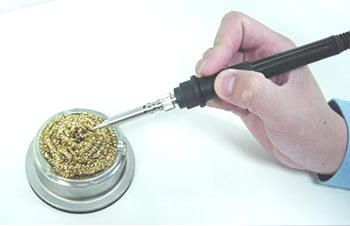
Using the ZD-987 was a DREAM compared to what I was using before. I mean really night / day. I practice awhile and even using that "test board" i bought before, I was quickly able to solder and desolder one of those sockets. Even my wife joined in, and was able to desolder with the gun. Extremely impressive kit.

It did take a few tries however, especially with pin 1 which I thought I sucked out the solder the first time but ended up putting solder back in (as per all those YouTube videos you guys mentioned before) so I could do it again. After a big of wriggling, I got out the old RTC. Soldering the new socket in was easier than I imaged with the new solder gun, used a smaller gauge solder this time as well. At the end the socket went in, even though I opted to bend the unused pins in stead of trying to clip them.

image2.jpg

Overall the whole process probably took less than 4 hours. I was shocked.

Moment of truth - I get a "CMOS Checksum ERROR" upon boot. I'm like... crap... that's all she wrote! I went into the BIOS, setup the new system time and rebooted again.

IT WORKED!

Booted into Win95... everything was back.

Finally!

Now... on to the ORIGINAL part of my plan... playing with the USB option in Win95. Perhaps a fools errand, given some of the stability issues, but hey - I've already proven how nuts I am with just the RTC chip.

Why stop now? ;)
 
Glad you enjoyed success. One golden rule that's oft-quoted: "You can't afford cheap tools." Now you understand why that's so. :)

Thanks. Indeed made the work quick and efficient with a positive result.

However I would have much more preferred the axiom or corollary to the golden rule: "If you can't do it yourself, pay a professional to do it for you." Just never had the luck to find anyone who could do the work, which would have been WAY less than I paid, not to mention the time I put in. :)

Anyway, on to the next chapter next weekend perhaps.

Cheers.
 
Back
Top