• Please review our updated Terms and Rules here

The Datapoint 5500 thread..

A quick update. Finally found the entrypoint for the RESTART routine. It is at 0175724. The bootstrap routine in there can boot from cassette, floppy, 9350 Cartridge disk and 9370 top-loaded disks. I only tested the cassette bootstrap and discovered that it put some requirement on the DECK READY signal that simulator didn't really fulfil. Now the DECK READY is delayed 1 ms and then it is able to bootstrap the simple little Games.tap file in 5500-mode booted via the 5500 RESTART code.
 
After yet another fix to the simulator it can now boot the DOS.C disks in 5500 mode. It seems that that the booting scheme differs between 5500 and 2200 with boot card. The floppy disk images at bitsavers seems to be of two types. 011.IMD seems to be bootable on a 2200 with the boot card while the rest boots on a 5500 with the built in firmware. 005.IMD is not bootable since it is corrupt, which is sad since it contains diagnostics. There is a missing sector on track 64. I wonder if I should relax the checking a bit so it can handle bad reads.
 
And the final installment of my re-engineering efforts : schematics of the backplane, the decoder_iii and an updated schematic of the mainboard. Changes are mainly to do with naming consistency across the different schematics.
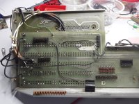
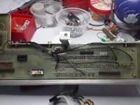
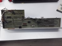
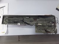
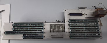
Also, for completeness sake, some pictures of the backpanel.
Note that this particular example has bad / dirty contacts in the connectors. Replacing them is not an option due to the dual PCB construction. I expect trouble when trying to run this unit....
 

Attachments

  • decoder_iii.pdf
    325.8 KB · Views: 2
  • DP5500_mb_v1.1.pdf
    1.7 MB · Views: 1
  • DP5500_backplane.pdf
    389.6 KB · Views: 2
  • backplane_detail.jpg
    backplane_detail.jpg
    2.8 MB · Views: 7
  • backplane_detail_2.jpg
    backplane_detail_2.jpg
    2.5 MB · Views: 4
  • backpnl_2.jpg
    backpnl_2.jpg
    2.3 MB · Views: 3
  • backpnl_1.jpg
    backpnl_1.jpg
    2.2 MB · Views: 7
  • backpnl_f.jpg
    backpnl_f.jpg
    495.5 KB · Views: 7
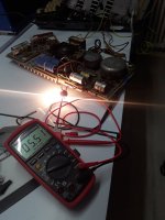
With the finished schematics of backplane and decoder it is on with the hardware itself : fixed mains switch and tempguard, reconditioned main caps, checked main transistors, and presto : +5V is present ! Sometimes its easy....
But always keep in mind that the design is really very dangerous. Need to fix a bunch of broken wires on the voltage connector, and then replace some mechanically damaged transistors and some RAM's that have fallen victim to a mouse.
 

Attachments

  • ps_5500.jpg
    ps_5500.jpg
    914.6 KB · Views: 7
Back
Top