• Please review our updated Terms and Rules here

PC LPT Port Interface Projects

syzygy

Experienced Member
Joined
Apr 22, 2023
Messages
415
Location
North East USA
I wanted to start a thread about home-brew / DIY / hobby projects that were built to plug into the PC Parallel Ports (LPTs). I did a few of these myself and they were very common in the hobby world and of course there were many products, other than printers, sold that plugged into the LPT ports. Rather than those products, I mean the stuff that so many would just make themselves. It was a very cool time and the idea of "real world interfacing" was a big deal - at least to me. I have a few projects to enter here and I will but I would enjoy seeing one's that other folks made as well.
 
I am an avid lover of music - always was and, I hope, always will be. I have no musical talent with respect to making music. The sound chips in the late 80s intrigued me.


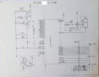
This is an AY8912 project that I did in Jan, 1988. I resurrected it and was using on my PC XT Clone. The chip was available from RS and I recall different versions that had an I/O port on the chip. I remember building several but I could only find a schematic that I made with the AY8910A.
PSG schematic Jan 88 20240309_140036.jpg

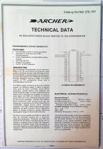
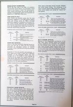
The RS version came with a data sheet which included instructions (of a sort) to make some sounds. I just can't remember if they also sold the 9812.
rs data 20240309_141151.jpg
data sheet sound effects 20240309_141117.jpg
It was that part of the data sheet (plus some others from GI) that led to the demo that I linked.

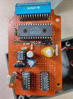
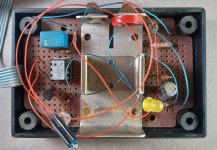
I used a project board that was sold at RS and came with the circuit board.
board 20220612_114148.jpg
bottom board 20220612_113743.jpg

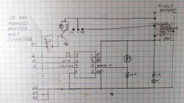
The complete source and executable is attached (TurboC 2.0). I recompiled it and simply removed some ID info - but everything else is as it was in 1988. One thing that I thought was clever, was the way I figured out what LPT port it was plugged into....

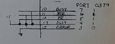
LPT selection 20240309_140036.jpg

By forcing some signals, I could read each of the three common port addresses from within the code - hey it worked for me :)
C:
char what_port()
/* returns the LPT# of the PSG [0 if not found] */
/* currently checks only LPT1 & LPT2 */
/* NOTE: There should be a BIOS call or location that reports where */
/* the printer ports will be if present! */
{
  if((inportb(0x03bd)&248)==240)
    return(1);
  else if((inportb(0x0379)&248)==240)
    return(2);
  else if((inportb(0x0279)&248)==240)
    return(3);
  else
    return(0);
}

I also see that I had to account for Turbo speed on the XT (which is all that I had). It still works. So as long as you don't hit the Turbo button after it loads it will play at the right speed. My XT clone is 10MHz turbo but back then it was 8 MHz.

Good times..and I can't believe I could figure out what I did decades later.
 

Attachments

  • PC_AY8912.zip
    23.2 KB · Views: 4
Last edited:
I think you know about this one already as I once used the parallel interface as a boot option, similar to what XTIDE has over the serial port, this one a tiny bit faster: to boot a late 1980s ARCNET diskless thin client over the "laplink" cable, switching to an INTERLNK session once CONFIG.SYS loaded. Later I did it the "official" way, with the guts of a 286 system acting as a DOS NetWare ARCNET server. Unfortunately I had bad RAM chips in it, so it was throwing parity errors all the time. The founder of the company and also one of the designers was pleased to see his product booting in the 21st century the way it should, and the way they didn't imagine it doing back then :)

And the obligatory Covox mash-up, to try playing .MODs on an 8088. Software emulation of the Tandy Sound Source and the Disney Sound Source thru the Covox was successful on a faster machine.
 
Last edited:
I wanted to start a thread about home-brew / DIY / hobby projects that were built to plug into the PC Parallel Ports (LPTs). I did a few of these myself and they were very common in the hobby world and of course there were many products, other than printers, sold that plugged into the LPT ports. Rather than those products, I mean the stuff that so many would just make themselves. It was a very cool time and the idea of "real world interfacing" was a big deal - at least to me. I have a few projects to enter here and I will but I would enjoy seeing one's that other folks made as well.
I made a Covox Speech Thing clone back in the day. Not very exciting, but it did sound better than I expected. I think I used 2% resistors. Later I made a stereo version that used two parallel ports.

I also interfaced with an HD44780 LCD over the parallel port. Nothing much to that either, although I wrote a TSR that would read video memory and send the characters to the LCD. So you could use it with DOS programs. As much as you can "use" a 20x4 display anyway.
 
Two of my projects come to my mind: CBM-HD and CBM-PC. CBM-HD emulates a Commodore 9060 hard disk drive plus several floppy drives. Remark: it also needs a COM port. CBM-PC emulates a Commodore 8032 computer and can be used to create images from real floppies. Of course one needs the floppy drive for that floppy as well.
 
I made a Covox Speech Thing clone back in the day. Not very exciting, but it did sound better than I expected. I think I used 2% resistors. Later I made a stereo version that used two parallel ports.

I also interfaced with an HD44780 LCD over the parallel port. Nothing much to that either, although I wrote a TSR that would read video memory and send the characters to the LCD. So you could use it with DOS programs. As much as you can "use" a 20x4 display anyway.
I never had a speech thing or really did much d2a at least back in the day. But, while I agree that it was no big deal, in the 80s that stuff was passing on info to non-EEs, that had previously only been in the realm of the EE. I always felt that was an important step as it opened up a lot of doors. Plus, it was a lot of fun.
 
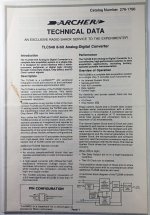
At one time, RS had sold a serial analog to digital converter - TLC548. I liked the idea and had no experience with one at the time.
TLC datasheet 20220810_135347.jpg

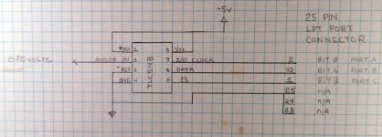
So I cobbled together a schematic...
TLC schematic 20220810_135412.jpg

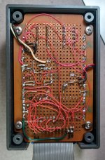
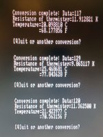
and began playing around. The code was kind of difficult to wrap my head around, but pretty soon I was getting reasonable values. Eventually, I decided that I would build a temperature sensor using a thermistor, that RS also sold.

tlc548_1_20220604_172947.jpg
TLC original 20220604_173038.jpg
TLC final schematic 20220810_135433.jpg

So, the program would operate a transistor which would operate a relay using a 9v battery to supply power to the circuit. Originally, I did not use a l05 regulator and instead used a 5v zener. This worked, as long as I did not turn it on too often because, the zener wattage was way to small for the circuit and it would get hot if I was taking samples 1/sec.

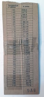
The thermistor card giving resistance vs. temperature presented a problem for me.
r card 20240310_190554.jpg

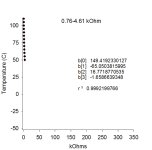
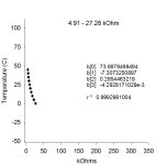
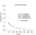
I couldn't get a good fit using a polynomial (I knew jack about nlin at the time) and I ended up taking a usable portion of the function that I could fit well. I felt like it was kind of cheating, but it was what I could do at the time. When I went through it recently, I confess that I felt compelled to fix that and I divided the function up and fit cubic polynomials to each one - the r2 values were excellent.
Thermistor low.jpgThermistor mid.jpgThermistor high.jpg
So I just now, modified the original code to incorporate that better way. Other than that, the code is pretty much the same as when I wrote it in late 1988 - good to know that I learned something in the last 34 years.
 

Attachments

  • New PC code.zip
    23.1 KB · Views: 1
Last edited:
Nice! I had to go here and checked out the article. You used a ZN426E8 - I had never even heard of it! BTW: do you still have one of the boards?
Yes in fact I used it recently to demo a few things on 'retro' comps:
Simple sampling:
Richard Russell's Music compiler (RR of BBC Basic fame)
SounDAC on the RC2040 (skip to 2 minutes 6 secs:
 
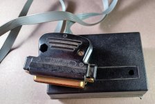
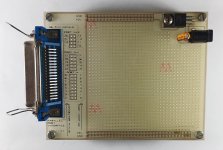
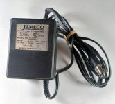
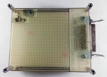
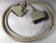
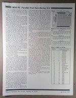
A couple of years ago, I was cleaning house and put some stuff on the bay. This was well before I had my new ,old XT clone. One item did not sell - this from Jameco - an interface board for PC LPT projects. I bought it and never used it at all. I am glad it didn't sell as I think I will use it for some new projects.


cover 20220528_161600.jpgPS 20220528_162648.jpgunderside 20220528_161615.jpgcable 20220528_161857.jpginstructions 20211005_093540.jpg
 
Nice find and, in my case, a problem: should one keep it in its original state to show people what we had or use it for a project?

And as an another addition from my side: I started with a Commodore 64 but as soon I had a XT-clone I created my own assembler written in Turbo Pascal and used the printer port to send the result to the User port of the C64. Main reasons: bigger editor screen, much more memory so I could handle bigger files and binaries, due to the memory also a much faster compilation and more and faster storage. And after adding a 20 MB HDD, the sky was the limit.......
 
Nice find and, in my case, a problem: should one keep it in its original state to show people what we had or use it for a project?
Yeah, that is a consideration. I haven't done anything with it yet, but I could see putting some header connectors on the port pins and rails and then lay a breadboard over the pads so as not to solder them. It would be convenient for working on projects.

BTW: I think that I originally purchased it from the Dancon Electronics listed on the instruction sheets and not Jameco as I originally stated. I am, however, relatively certain that the Jameco wall wart is what was provided in the kit.
 
Last edited:
I built/maintain a system that runs an OPTO-22 interface board from the PC printer port to operate a 3 million BTU/hour boiler, circulator pumps, etc. in a greenhouse complex. Temperature and humidity sensors, as well as remote devices (e.g. unit heaters, fans, vent operators), are interfaced using Dallas 1-wire stuff. FreeBSD OS.
 
Last edited:
Regarding the OPTO-22 (I presume that you're talking about what is documented in the attached datasheet), I have one of those but haven't put it to any use. How did you wire it up to your printer port?
 

Attachments

  • OPTO 22 Datasheet (G4PB32DEC - G4 32-Channel IO Module Rack).pdf
    118.9 KB · Views: 5
HD44780 character LCDs on the parallel port were my introduction to programming for hardware.
 
Regarding the OPTO-22 (I presume that you're talking about what is documented in the attached datasheet), I have one of those but haven't put it to any use. How did you wire it up to your printer port?
I bought a fully populated PB16H rack on ebay for cheap (in 2009?), and made a cable to run from the 50-pin header to a DB25, wired to suit the PC LPT port. I ran +5V and ground from one of the Molex connectors inside the PC to power the rack. The FreeBSD PPI driver allows access to the status and data registers for both reading and writing.

I wouldn't think doing something similar with your G4PB32DEC rack would be any more difficult, but I don't expect you will be able to use all 32 channels without some kind of multiplexing.
 
Last edited:
While it was not a DIY kit I used, I would be remiss to let this thread pass without noting the parallel port to cassette adapters which had multiple similar designs springing forth in multiple countries over the span of a decade with poorly drawn schematics. The most interesting element to me was the alternate design incorporating a battery to deal with the parallel ports that didn't supply adequate power.
 
HD44780 character LCDs on the parallel port were my introduction to programming for hardware.
Ooh yes me too, I'd forgotten about that.
Code:
PAGE 58,132
CODE    SEGMENT
    ASSUME CS:CODE,DS:CODE,ES:CODE,SS:CODE
; Drive Hitachi display on LPT1. Data lines straight, STRB (1) --> E (6)
; SLCT_IN (17) --> R/W (5), AUTO_FD_XT (14) --> R/S (4)
; Ignore BSY signal (o/p only port), just delay after every operation.
; Phil_G Apr 96
;
PORTA   EQU 378h
PORTC   EQU 37Ah
;
    ORG 100H        ; a .COM file

BEGIN:  MOV DX,PORTA            ; Init port to zeroes
    MOV AL,0
    OUT DX,AL
    MOV DX,PORTC
    MOV AL,PORTCM
    OUT DX,AL
    CALL DELAY
    CALL DELAY
;
    MOV SI,OFFSET ITABLE    ; set-up command string
    MOV CL,ILEN             ; length
    MOV CH,0
IPRINT: CALL DELAY
    LODSB
    MOV DX,PORTA
    OUT DX,AL               ; OUT ASCII DATA
    CALL STROBE
    LOOP IPRINT

    CALL SETTXT             ; set text i/p mode

    MOV SI,82H              ; to string parameter
    MOV CL,byte ptr cs:[80h]; length
    cmp cl,0                ; nowt there?
    jz done
    dec cl                  ; less initial space
    MOV CH,0
MPRINT: CALL DELAY
    LODSB                   ; print message
    MOV DX,PORTA
    OUT DX,AL               ; OUT ASCII DATA
    CALL STROBE
    LOOP MPRINT

DONE:   MOV AX,4C00h            ; all done
    INT 21h

ITABLE: DB 30h,30h,30h,38h,08h,01h,06h,0Eh,06h
;ITABLE:        DB 38h,38h,06h,0Ch,01h
ILEN    DB ILEN-ITABLE

PORTCM  DB 00001011b            ; map of control port C

STROBE: MOV DX,PORTC            ; pulse E hi then lo
    MOV AL,PORTCM           ; note LPT inverts it
    OR AL,1
    MOV PORTCM,AL
    OUT DX,AL
    AND AL,0FEh
    MOV PORTCM,AL
    OUT DX,AL
    RET
;
SETTXT: CALL DELAY              ; set text mode by
    MOV AL,PORTCM           ; setting RS bit...
    AND AL,0FDh             ; note LPT inverts it
    MOV DX,PORTC
    OUT DX,AL
    MOV PORTCM,AL
    RET
SETCMD: CALL DELAY              ; set command mode by
    MOV AL,PORTCM           ; resetting RS bit...
    OR AL,02h               ; note LPT inverts it
    MOV DX,PORTC
    OUT DX,AL
    MOV PORTCM,AL
    RET

DELAY:  PUSH CX                 ; a few MS delay
    MOV CX,8000h            ; guess value?
DEL1:   LOOP DEL1
    POP CX
    RET

CODE    ENDS
END     BEGIN
 
Back
Top