• Please review our updated Terms and Rules here

IBM 8513 Monitor width

Maikudou

Experienced Member
Joined
Aug 21, 2023
Messages
75
Location
SF Bay Area
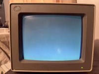
Hi, I have a 8513-001 monitor (S/N 72-0182100).
It works good, no burn-in, good converjence and focus, except the raster is too narow (to my taste, Maintenance manual says "at least 20cm", and it is exaclty 20cm max). The adjustment coil can be turned to make it even narrower, but not wider. It is like an inch less than the bezel width each side.
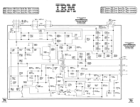
I learned the width is controlled by the coil _and_ some capacitors adjacent to it. I've measured every one close enough (I have the schematic from the web as well as troubleshooting guides which are googleable, I know about them, thanks) and they have good capacitance, but ESRs I am not that sure, for caps 225 0.22uF and 226 0.16uF (closest PP ones to the coil per schematic) the cheap ESR meter from Amazon says its ok, around 3.7 Ohm, "good", but I don't believe it, it measures 80 Ohm for 0.01uF, "bad", for new one fresh out of Mouser, which might not be true, probably it can't measure small capacitance cap reliably, it says either overload or 'bad" for anything smaller that 0.1 uF, I think. In and out of circuit.

The troubleshooting guide from the web suggests when having "width problems" suspect a couple of resistors (R305, R306) close to some chip, which I think unlikely? How often do 1/2W resistor fail anyway? And they measure to spec in-curcuit.

Did anyone succesfully fixed the width problem in this or similar monitors. I can replace all of the caps, but there are _a lot_, and I don't really want to cut the CRT PCB from the goo it is fixed with to put the main PCB out.

Also sides of the raster are not uniformly flat or uniformly pincushioned either way, it starts slightly wider, then arches to slightly narrower than back, almost like very narrow (1/8'') S shape, does it suggest what else can be at fault?

Thanks!
 
Last edited:
The width is significantly affected by the B+ voltage to the horizontal output stage. Have you checked that ? there is often a voltage control preset in the PSU section to set the PSU's output voltage. It could be around 10 to 15% too low.

The primary determinant of the width is the B+ supply voltage V, and the the yoke's inductance L. When the H output transistor (HOT) is switched on, the current rises at a linear and rapid rate of V/L many thousands of amps per second, but the total current doesn't rise more than a few amps peak because the HOT is forced into cut-off on the R side of the raster scan where the current has peaked, then flyback begins and the field reverses and the stored energy then scans the left side of the raster via damper diode current. It is the amplitude of the scan current on the R raster side, the sets the width on the L side too, the peak current value in the H yoke coils is simply reversed after flyback.

This is the reason why placing an inductor in series with the yoke reduces the width, because the total L value is increased so the fraction V/L becomes a smaller value, and the peak yoke current (horizontal coils) which sets the width of the H scan, is reduced because the current rises to a lower value in the same time frame. So you will find if you screw the slug into the width coil, increasing its inductance, it will reduce the width. Or if you take the slug out, you will be at max width that the width coil can allow.

If it is not possible to increase the PSU's output voltage (but it normally is), one trick I have used in the past is to simply short out the width inductor.

PS: ESR meters are not much good at checking capacitors under a few uF in value. This is because, in general, the test is performed at 100kHz, and for example a 0.47uF capacitor has a reactance at that frequency of about 3.4 Ohms, so that is the sort of result you might see on the ESR meter, but that is not the capacitor's real ESR, it is its impedance at 100kHz. You could only get the real ESR value with a test instrument that performed the test at a much higher frequency for low value capacitors. Generally ESR meters are only any chop for checking caps above 5 to 10uF. A 0.01uF capacitor could well read up to 160 Ohms on a typical ESR meter and still be perfectly ok.
 
Thanks! That’s a lot of useful information, there is indeed an adjustable pot in the power supply, I’ll see if it does anything after I check the B+ voltage.

The slug in the inductor turned all the way in (in direction where width increases to its current max), at this stage it is in a “leg”, below the actual coil, so I think shorting it won’t help much, unfortunately.
 
The width is significantly affected by the B+ voltage to the horizontal output stage. Have you checked that ? there is often a voltage control preset in the PSU section to set the PSU's output voltage. It could be around 10 to 15% too low.
Something that I've always wondered: does increasing B+ voltage also increase the CRT (anode) voltage? Or is that regulated in some other way? Is there a point at which increasing B+ becomes dangerous i.e. causing the CRT to emit x-rays? I have an old SVGA monitor that suffers from narrow width, and tweaking B+ definitely does restore the width to "normal", but without knowing what the original B+ voltage should have been (no service manual) I am wary of actually using it....
 
Thanks! That’s a lot of useful information, there is indeed an adjustable pot in the power supply, I’ll see if it does anything after I check the B+ voltage.

The slug in the inductor turned all the way in (in direction where width increases to its current max), at this stage it is in a “leg”, below the actual coil, so I think shorting it won’t help much, unfortunately.

Can you post the schematic of your VDU ?

Also, often with a width coil, the body of the coil can be fairly high up on the coil former, meaning that if you screw the slug right in, past the center of the coil body, the inductance can decrease again, in a similar manner that it does poking out the top of the coil.
 
Last edited:
Thanks! That’s a lot of useful information, there is indeed an adjustable pot in the power supply, I’ll see if it does anything after I check the B+ voltage.

The slug in the inductor turned all the way in (in direction where width increases to its current max), at this stage it is in a “leg”, below the actual coil, so I think shorting it won’t help much, unfortunately.
The minimum inductance will still be present even with the ferrite fully out of the coils (its still a coil of wire) so shorting should still reduce the inductance.
 
Something that I've always wondered: does increasing B+ voltage also increase the CRT (anode) voltage? Or is that regulated in some other way? Is there a point at which increasing B+ becomes dangerous i.e. causing the CRT to emit x-rays? I have an old SVGA monitor that suffers from narrow width, and tweaking B+ definitely does restore the width to "normal", but without knowing what the original B+ voltage should have been (no service manual) I am wary of actually using it....
Yes it does, all else equal if you increase the width by manipulating the B+ voltage, the EHT increases, this has the effect of reducing the width, but not linearly. All else equal, the scan width (in a magnetically deflected CRT) is inversely proportional to the square root of the EHT voltage. So you get a mixed effect increasing the B+, because while the peak deflection current increases, increasing the width, the width is reduced by the square law relation relating to the EHT. (Generally the B+ and EHT voltage are linearly related). So in effect, what you end up with, is the scan width not being linearly proportional to the B+ voltage, but rather to the square root of it. So, to increase the scan width by about say 10% you have to increase the B+ to about 1.2, not 1.1.
 
its still a coil of wire
Right, of course, I am a bit slow.

Here are the schematics, PSU pot says it's "B+ ADJ', and I see B+ voltage should be 115V, or is it something different?
 

Attachments

  • IBM 8513 Monitor Schematic.png
    1.6 MB · Views: 3
  • IBM 8513 Monitor PSU Schematic.png
    IBM 8513 Monitor PSU Schematic.png
    933.7 KB · Views: 3
Last edited:
Adding to kdr's comment, should I dial screen voltage pot on the CRT down when I crank B+ up?
Probably it's best to check what the voltage is. I imagine it is better to measure it under load? Does it matter, if so what would the best point to get it, somewhere around R416 or R994, the first components after 115V gets into the board?
Measure the 115V on the meter, if it is lower than that increase it to 115V. Re-check the width. If it is already 115V you could increase that to say 120v with little if any risk, though I would not set it higher than that initially at least. Then see what happens with the scan width.

If you do have to end up shorting out the width inductor, I would recommend setting the PSU to maybe around 100 to 105v for the test. and then increasing it afterwards for the correct width. Also make sure it is just the width coil that gets shorted not the linearity inductor as well.

Also in these sets the scan width is dynamically modulated , in this case via collector of Q303 and primary of transformer T402, its secondary being in series with the yoke circuit. Usually though if the width was decreased by a failure in that circuit is becomes obvious because the visible sides of the raster scan are not straight.

Also, check that resistor R418 (3.9 Ohm 5W) is still in spec, since it is in series with the S correction capacitors (C425/426). If that resistor went high, the width would drop.
 
Last edited:
visible sides of the raster scan are not straight
I would say they are not exactly straight, and I think it also becomes slightly more narrow from top to bottom.
Adjusting B+ does make it wider, although it was almost at max, about 15 degrees back from max, haven't measured V yet. Maxing it out makes it wider then the bezel, so I turned it back for now, until I know the voltage.
I'll do the proper measures and other things you have suggested to get some new info.

I am a bit new to low-level electronics and insides of CRTs in particular, what's "S correction" in two words? Just curious.
Two words, impossible, unless perhaps "Linearity fix"

The coupling capacitors (called S correction caps) in series with the H yoke coils don't just block DC, they put an S curve like bend in the H scanning current (by resonating with the yoke's inductance) that is like a section of a sine wave + and - 90 degrees. So what it does, is that it slows down the rate of change of current with time on the R and L side zones of the raster scan, and speeds up the rate of change of current with time in the raster center area, across the H meridian. This effectively compresses (crowds) the scan linearity on each side and stretches or expands it in the center area. This is because, without that, the scan linearity you would get would be crowded in the middle and stretched towards the L & R sides, the reason for that being; the sensitivity of the deflection yoke to an applied current increases with the scan angle.

The S correction is not the only requirement for good H scan linearity. The other is a magnetic coil with a non-linear response due to the permanent magnet in it. This is required because without it, the scan on the left side of the raster is stretched compared to the right. This relates to the fact that when the field is building up on the R side of the scan, it is partially an inverted exponential process, where the rate of change of current falls away a little with time (not a perfect linear sawtooth current), so that the rate of change of current with time is lower near the R side of the raster than the middle (this assists the yoke sensitivity issue). But, on the L side, it is a decay process where the magnetic energy is returned to the power supply via the damper diode, and this process is more rapid at the extreme L of the scan, and slower towards the middle, aggravating the Yoke's sensitivity issue. The magnetic Lin coil allows the L side of the scan to be compressed and match the center and the R side linearity.
 
R418 is 4.4Ohm, 12% more than it should be. I see this kind are usually rated at least 5%, so it is way off.
B+ voltage was more or less ok, making it 120V makes width bigger but not filling to full width. Cranking to 125V makes it filling the whole tube, but I think it might be too much.

This is the maximum width what I can get at 120V and slug adjustment (all the way in below the coil or all the way out of the coil). Its IBM's built-in test scan what it shows when not connected to anything, it corresponds to geometry it shows when connected to a VGA source pretty closely.

Do you think 12% more resistance in R418 might affect it to this degree? I'll try to source one and replace.

Thanks a lot for the education, that was very helpful!
 

Attachments

  • IMG_2958.jpg
    IMG_2958.jpg
    3.7 MB · Views: 7
R418 is 4.4Ohm, 12% more than it should be. I see this kind are usually rated at least 5%, so it is way off.
B+ voltage was more or less ok, making it 120V makes width bigger but not filling to full width. Cranking to 125V makes it filling the whole tube, but I think it might be too much.

This is the maximum width what I can get at 120V and slug adjustment (all the way in below the coil or all the way out of the coil). Its IBM's built-in test scan what it shows when not connected to anything, it corresponds to geometry it shows when connected to a VGA source pretty closely.

Do you think 12% more resistance in R418 might affect it to this degree? I'll try to source one and replace.

Thanks a lot for the education, that was very helpful!

If everything was normal, probably the width would be ok with the supply output at 115V and the width coil about with the slug partially into the coil. So something else I think must be going on.

I would put the PSU back to 115V now.

R418 being high in value will result in some loss of width, how much though, we would only find out when you replaced it.

I'm beginning to wonder if the east-west modulator is working, the side of the scan looks like it has some barrel distortion (although it is conforming to the escucheon shape, that is curved, the raster should be a perfect rectangle when you can see it under-scanned). Perhaps transistor Q303 has failed or lost its drive. Also check resistor R336 in series with the collector circuit and primary of T402.

Is there any effect on the shape of the side of the raster if you adjust the preset R327 ? This alters the amplitude of a parabolic shaped waveform that drives T402.

Do you have a scope ?
 
R336 is in spec, did not check the Q303, it's in the middle of the board, hard to get to
R327 PCC AMP makes it cave inside or push outside in pincushion/barrel shape
R328 PCC PHASE makes it either narrower at the bottom like a prism, or almost square, still a bit narrower at the bottom is as close as it gets to a square

I've ordered some resistors will see if it helps in any way.

No, I don't have a scope yet :)
Well that is good at least we know that the E-W modulator is working.

It may be a matter of shorting out the width inductor and increasing the B+ (115V) just enough to get full width.
 
The width of the raster in your picture looks completely normal to me. Monitors from that era underscanned a lot more than later CRTs. "Edge to edge" scanning didn't become a thing until CRTs had square corners.
 
Yeah, it has crossed my mind, but this pic is when B+ voltage is 120V+ instead of 115V it was designed for, I prefer my devices to operate in spec if it's possible to fix without too much work. If not, I surely can live with it.

When it's 115V it's a full inch underscan both sides. I have another monitor of this model but version about 3 years older and it scans full without cracking B+ voltage, it is slightly different there is no coil to regulate width, it's a pot. Too bad it is so burned in I can see what kind of airplane tickets they used to sell. So I think something is not quite right with this one, hopefully it's just a resistor, we'll see tomorrow when it comes.
 
Wen your replacement resistors arrive, one thing you could try is paralleling two of them, to halve the value, and also check if that has any appreciable effect on the width.
 
My own IBM 8513 also had quite a lot of border area... except in 650x350 EGA mode, which was vertically stretched and nearly filled the full height of the screen. It was like that since the monitor was new.
 
Back
Top