Maikudou
Experienced Member
Maybe I don't understand something about resistors. I got 10 x 10W (5W was unavailable) 3.9J (5%) resistors, and all of them measure 4.5 Ohm (15%, three times more than 5% allowed). Is it ok? Maybe they are supposed to loose resistance when they warm up or something, or are they just bad, manufacturer decided to put more resistance for the same price?
BTW, adding it in parallel yelding, if I understand correclty 1/(1/4.4 + 1/4.5) = 2.2 Ohm (measured, it is 2.2) and it did not affect the width in any way.
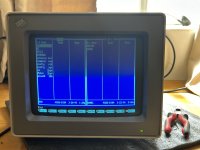
On the plus side, my fiddling probably dusted off something somewhere and now it is at OK-ish width (1/4 '' each side) at 115V B+, so I am good.
Thanks everyone for help!
BTW, adding it in parallel yelding, if I understand correclty 1/(1/4.4 + 1/4.5) = 2.2 Ohm (measured, it is 2.2) and it did not affect the width in any way.
On the plus side, my fiddling probably dusted off something somewhere and now it is at OK-ish width (1/4 '' each side) at 115V B+, so I am good.
Thanks everyone for help!