• Please review our updated Terms and Rules here

IBM 8514 problems

scroeffie

New Member
Joined
Feb 11, 2024
Messages
9
i did a full recap replaced the degauser block 'monitor turns off after couple of sec
i tested the flyback by disconnecting the neckboard monitor stays on so flyback is stil good !
friend says x ray protection is kiking in and shuts down the monitor
any one has a schematic for a

IBM 8514​


thanks

 
How did it work before the recap? Is this a new problem, or something you were hoping to fix with new capacitors?

It's hard to see a lot from your shaky vertical video, but it looks like there's a lot of over scan (DOS text is cutoff on the left). This monitor should under scan about 0.5-1" on all sides. This could indicate a power supply, or HV issue. Excess HV will usually cause the raster to shrink, and low HV will cause it to expand. High B+ from the power supply could cause it to expand like that.

Second thing I noticed was that the power light went off when it shut down. Normally, X-ray protection just disables the HV, not the entire power supply.

Over scan plus the power supply shutting off would lead me to think the power supply has a problem. Check the output voltage to see if it's in spec.
 
i did a full recap 90% of the caps where dead like 100% dead ,i left 2 original caps in they where both bp caps and wel in spec ,the overscan is because i touched one of the rings putting back in the case
i know dumb ,friend says its x ray kiking in and or film caps dead he also says could be B+ problem
yes i had this problem when i got the monitor ,it was free dumbster find
with out a schematic not shure what to do anymore
i dont want to give up its a nice looking monitor
 
I agree with Andy.

Any "rings " whatever you are referring to that you have touched won't affect the H scan width. It will be affected by the B+ voltage and the width coil mainly, this has an adjustable ferrite slug normally (better left alone)

The X-ray shut down system is normally monitored by measuring a small proportion of the EHT voltage.

Since all other things equal, the size of the raster scan is inversely proportional to the square root of the EHT voltage, so if the EHT voltage had gone intermittently too to high on its own, the size of the raster scan, would have been seen to get smaller just prior to the shutdown. On the other hand, with excessive B+ voltage, this pushes the EHT voltage up and increases the scan width and it could be that it is in a borderline condition, just enough to trigger the X-ray shutdown system.

So, the main thing is as Andy says, check the B+ voltage out of the power supply section. There is normally a preset that adjusts its value. You need to find the schematic to find out what the B+ voltage supplying the Horizontal scan & EHT generator stages is. We know from a recent post about a similar model, the 8153 that it was 115V. But your exact model needs to be checked.
 
I agree with Andy.

Any "rings " whatever you are referring to that you have touched won't affect the H scan width. It will be affected by the B+ voltage and the width coil mainly, this has an adjustable ferrite slug normally (better left alone)

The X-ray shut down system is normally monitored by measuring a small proportion of the EHT voltage.

Since all other things equal, the size of the raster scan is inversely proportional to the square root of the EHT voltage, so if the EHT voltage had gone intermittently too to high on its own, the size of the raster scan, would have been seen to get smaller just prior to the shutdown. On the other hand, with excessive B+ voltage, this pushes the EHT voltage up and increases the scan width and it could be that it is in a borderline condition, just enough to trigger the X-ray shutdown system.

So, the main thing is as Andy says, check the B+ voltage out of the power supply section. There is normally a preset that adjusts its value.
i dont know how to test the b+ voltage :)
 
I am not as knowledgable as Hugo, but I checked mine by probing the point where b+ comes to the board (looking at schematic, but one can figure it out by looking where the psu leads go) and ground. Please exercise usual precautions when working with electrical appliances when doing that.

I am not sure if you can simply check unconnected PSU as it seems your model does not have PSU as a separate unit. I guess you can look for a pot with B+ on it and see if it is not cranked all the way up and see if dialing it down helps in any way with overscan and shutdowns.
 
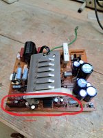
I found my problem these optocouplErs are dying and getting hot .but i dont know where to find a replacement there is no schematic ibm monitor


How do you know the opto-couplers are dying ? there is no scientific evidence presented.

Just because they are getting hot doesn't mean that they are dying or dead. If anything, one with an open circuit LED would be as cold as a cucumber as it would be if the LED were shorted out. If the output transistor was shorted out, or even open for that matter, in both cases, the heat dissipation would be negligible. In fact I cannot think, off hand, of a common failure mode that could possibly cause an opto-coupler to overheat unless, for some reason, the transistor was in a state of partial conduction and a high current was applied. Or a massive LED over-current, but the LED current is normally limited with a series resistor. It is not very plausible.

To test them they would need to be removed, placed in a test jig with a suitable current limiting resistor, and to be safe to limit the LED current to less than 10mA to 20mA and place a load resistor in series with the transistor and a supply voltage, and look with the scope or meter to see of they were working, or not. The transistor should conduct when the LED is energized. You can also check the LED voltage drop to help confirm the internal LED's are ok. Look up the electrical properties of opto-coupler ICs/modules.

I'd be a little more suspicious of the thick film module nearby that looks like it has suffered from some heating effects.
 
you mean those 2 dark thin things with components inside of them ? we did not do any test friend is a electrical engineer has allof of crt experience ,but we are not shure its not caps or resistors or diodes
so whats left ? these 2 optos or the long thin things with components inside of them ,with in 5min the monitor is 100% stable ,also sometimes i cant start the monitor from cold start i turn it on does nothing i turn it off than i wait couple of sec than i can turn it on something is way out of spec or almost dead ,with out a schematic i have no idea what these parts are or what replacement to buy (y)
 

Attachments

  • 439575735_3370765956553934_5210117564484358405_n.jpg
    439575735_3370765956553934_5210117564484358405_n.jpg
    420.9 KB · Views: 4
The "long things with the components in them" are thick film modules. These can be awkward in cases where the manufacturer has not published their contents. Generally they contain a few transistors and surface mount resistors & capacitors mounted on a white ceramic substrate, then that arrangement is dipped in resin. In the past, in undocumented cases, I have had to remove the resin and document the contents, so a to build a replica, without the resin that is.

Currently though, there is no test data that suggests the modules are faulty, or the opto-couplers are faulty for that matter, they may well be ok.
wil buy a scope and test some more we cant think of anything else
 
Back
Top