I meant your mailing address so I could get you a shipping quote
Upcoming Events:
- VCF South West - June 14 - 16, Davidson-Gundy Alumni Center at University of Texas at Dallas
- VCF West - Aug 2 - 3, Computer History Museum, Mountain View, CA
- VCF Midwest - Sept 7 - 8 2024, Schaumburg, IL
- VCF SoCal - Mid February 2025, Location TBD, Southern CA
- VCF East - April 2025, Infoage Museum, Wall NJ
-
Please review our updated Terms and Rules here
You are using an out of date browser. It may not display this or other websites correctly.
You should upgrade or use an alternative browser.
You should upgrade or use an alternative browser.
Cromemco JS-1 Joystick Replica
- Thread starter nullvalue
- Start date
Hugo Holden
Veteran Member
Yes, I asked him about ordering 8 and if he would ship to AU. The shipping is somewhat fierce at $39.30 USD (which is about $60 something AU). Yes I will ask to to make up other listings for 8, if I buy them.LOL @Hugo Holden I just happened to go back to guy's listing and now there's a 8-switch listing, was that by request from you? I'm gonna order from that listing tooExcept it looks like there's not multiple quantities available. Could you ask him to keep it listed for another order?
Hugo Holden
Veteran Member
I meant your mailing address so I could get you a shipping quote
It is PO box 93, Buddina, Queensland, post code 4575.
I've got GlobalPost Standard (6-10 days) coming in at $20.31 USDIt is PO box 93, Buddina, Queensland, post code 4575.
Last edited:
Hugo Holden
Veteran Member
That does seem a lot better, maybe I could buy 8 switches and 8 of the keycaps through you somehow and have them shipped for some more than that, could that work ?I've got GlobalPost Standard (6-10 days) coming in at $20.31
Yeah that'd be fine! I'll dm youThat does seem a lot better, maybe I could buy 8 switches and 8 of the keycaps through you somehow and have them shipped for some more than that, could that work ?
Hugo Holden
Veteran Member
I could email the switch seller and ask him to change that listing to 16 switches and explain that you would be getting them ?Yeah that'd be fine! I'll dm you
I could email the switch seller and ask him to change that listing to 16 switches and explain that you would be getting them ?
Sure sounds good
Hugo Holden
Veteran Member
I think what we should do with the audio and speaker issue for the replicas:
Since there is a tag strip assembly there, we simply add another identical one beside it. There is room. It will carry the components for the class-B amplifier and we will make it with the period correct transistors. I will finalize and test the design and do the layout of it on the added tag strip, so as to make it at least look like it belongs to the era this unit was made.
This way we can get more audio power into an 8 or 16 Ohm speaker.
I think this is likely needed anyway. My assessment of the original system with the 45 Ohm speaker only being any good to the tune of about 50mW at best, suggests that it would have a very modest volume, about that of a small transistor radio, likely ok in a quiet room, but not enough if it was a noisy environment. It needs a little more steam.
Does anybody know a good link to the D+7A board schematic ? The one I found on S-100 computer was not really clear enough.
syzygy
Experienced Member
Is this one better?Does anybody know a good link to the D+7A board schematic ? The one I found on S-100 computer was not really clear enough.
Just my two cents....I'm not doing the work, but if my understanding is correct, the audio is TTL level initially, with a, somewhat weak amplifier, in the case of the console version. Why not just take the audio bit and GND to a terminal or an external jack? This leaves the design almost identical to the original (assuming that you duplicate the 45 ohm speaker and amplifier as per the console) and allows the end user to use an external amplifier of their choosing? Again, just an opinion.
Hugo Holden
Veteran Member
I'm not sure that it is "TTL". I have only just seen a version of the schematic I can read (Thanks for that link) .Is this one better?
Just my two cents....I'm not doing the work, but if my understanding is correct, the audio is TTL level initially, with a, somewhat weak amplifier, in the case of the console version. Why not just take the audio bit and GND to a terminal or an external jack? This leaves the design almost identical to the original (assuming that you duplicate the 45 ohm speaker and amplifier as per the console) and allows the end user to use an external amplifier of their choosing? Again, just an opinion.
It looks to me so far that the audio signal is derived from the output of the DAC and passed via CMOS selectors that are not digital, in the sense that they act like analog transmission gates. But I am still working the circuit out.
The selected analog output feeds the transistor driver(which feeds the speaker). Since they had it feeding an emitter follower running from the 5V rail in the 45 Ohm speaker case, it is unlikely the dynamic voltage dipped below zero volts (but I don't know, it could potentially go close to -5V). But probably the pp voltage swing there is 5V. If it was larger that would cut the transistor off, making for nasty sounds. This could make the 100R speaker connected to -5V a much better option than the 45 Ohm version connected to ground.
I think the trick is to make the audio driver for the speaker accept a pp input amplitude of close to 10V without any significant distortion, then it will be ok whatever the case of the driving signal.
syzygy
Experienced Member
Are you still looking for someone to cut your panels for you? I'd be happy to take a run at it.
Really? yeah that would be awesome.. I did acquire some (cheap) diamond files and was considering doing it by hand but I have no experience with this kind of thing. If you have done this kind of work before then that would be great. What would you require? I'm assuming you'd need some kind of printable cut pattern/template?
DougM
Experienced Member
- Joined
- Apr 20, 2023
- Messages
- 98
Just the box and a drawingReally? yeah that would be awesome.. I did acquire some (cheap) diamond files and was considering doing it by hand but I have no experience with this kind of thing. If you have done this kind of work before then that would be great. What would you require? I'm assuming you'd need some kind of printable cut pattern/template?
Let me know if you need more details on what the drawing should look like.
Yeah I'd rather not guess so if you have some examples on a format you'd prefer, please let me know.Let me know if you need more details on what the drawing should look like.
As if we don't have enough parallel conversations going on, I wanted to throw out one more question - that is what's the best way to do the decals/logo? At one point, I had tried the toner transfer/acetone method (for a different project) with some iffy results, at best. However I'd be hesitant to even try that method here because the enclosures are pre-painted and I wouldn't want to risk the acetone damaging the paint. Does anyone have any suggestions on how to do decal transfer onto painted metal?
Last edited:
wperko
Experienced Member
- Joined
- Jul 4, 2007
- Messages
- 407
Hi,
R/C radios are setup for airplanes, helicopters and boats ... the left arm is throttle up 'n down so that's why it doesn't return anywhere, the left right function is rudder so after the turn, the rudder needs to return to straight.
.
R/C radios are setup for airplanes, helicopters and boats ... the left arm is throttle up 'n down so that's why it doesn't return anywhere, the left right function is rudder so after the turn, the rudder needs to return to straight.
.
DougM
Experienced Member
- Joined
- Apr 20, 2023
- Messages
- 98
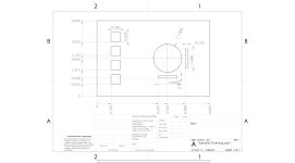
Here's what I usually put together before I head down to the shop. Obviously all of these numbers are made up.Yeah I'd rather not guess so if you have some examples on a format you'd prefer, please let me know.
Once I have the thing programmed into the machine I can cut a sample faceplate and you can test fit before I actually try to cut the box. That might avoid $34 mistakes.

DougM
Experienced Member
- Joined
- Apr 20, 2023
- Messages
- 98
The 8-bit Guy on YouTube talks about those quite a bit, you might be able to find good ideas there.what's the best way to do the decals/logo?
I'm curious about this too.

