• Please review our updated Terms and Rules here

Cromemco JS-1 Joystick Replica

Here's what I usually put together before I head down to the shop. Obviously all of these numbers are made up.

Once I have the thing programmed into the machine I can cut a sample faceplate and you can test fit before I actually try to cut the box. That might avoid $34 mistakes.

Wow this is great, thanks! In fact when I send you the enclosures I'll also include a keyswitch and joystick so you can do a test fit on your end. I should have the enclosures next week and won't take much longer to get you the right measurements. Thanks! What kind of machine are you using to do these cuts?
 
The 8-bit Guy on YouTube talks about those quite a bit, you might be able to find good ideas there.

I'm curious about this too.

I was playing around with a spare piece of painted metal this morning with the toner transfer method and using just heat without much success.. The I was thinking how an actual laser printer works, and it applies heat from the other side of the paper. I was applying heat directly to the label and trying to transfer. So instead I tried heating from the other side of the metal (with a Hot-Air Rework Station and no nozzle installed) and applying at the same time and got some better results! Messed up a bit on the Cromemco but I think with some more practice I can get this down... the larger the print, the harder it is to get even, but that "Cromemco" is about 3" long which is much bigger than anything on the JS-1. The only thing is that while the text can't be rubbed off with a finger, it can be scratched off rather easily with a fingernail. I'm thinking I'll need to apply some kind of clearcoat?

PXL_20240417_204704350.MP.jpg PXL_20240417_205040346.MP.jpg
 
Last edited:
On the Calcomp box logo thread recently, I suggested blank waterslide decal material which you colour laser print onto:
https://www.ebay.com.au/itm/293826764299
I have a few sheets of this somewhere, but sadly no access to a colour laser any more.
Oh those look nice.. how durable is the transfer? do you still to do a clear coat? nvm just read the instructions, they say to apply a clear acrylic spray afterwards.. I'll get a few sheets to experiment with.
 
Last edited:
On the Calcomp box logo thread recently, I suggested blank waterslide decal material which you colour laser print onto:
https://www.ebay.com.au/itm/293826764299
I have a few sheets of this somewhere, but sadly no access to a colour laser any more.
I was going to suggest those too ! A great product. The stickers you can make from it normally adhere well and are durable.
 
They are Gantry CNC machines, sorta home made...

In this picture you can see the little one in the foreground and the big one in the background.
Wow, great setup! I have a small "desktop" CNC machine.. it's fine for dabbling but I barely know how to use it.
 
Here's what I usually put together before I head down to the shop. Obviously all of these numbers are made up.

Once I have the thing programmed into the machine I can cut a sample faceplate and you can test fit before I actually try to cut the box. That might avoid $34 mistakes.View attachment 1278102
That is great. Ir would save 99.9% of the work getting it done, compared to by hand.

Doing it with a routing tool though: the diameter of the small one is about 1.5mm (I think, or similar) So, unlike a square punch, it is not possible to get a perfectly rectangular hole corner. This is where the small diamond files come in handy.

Each of the switch holes has a small shallow rectangular cutout in the perimeter on two edges, I think allow for the side retaining projections on the Cherry switch body to pass through, the size of that I think is on the datasheet for the switch. Probably these would require a small touch up with the diamond file because of the radius of curvature of the milling tool.

In my instance I have bought the Hammond cases locally in AU, so I'm probably going to do it by hand after the correct dimensions are agreed on.

From the switch data sheet, the hole dimensions. They have an error range, but selecting the smaller of the values, I converted them to mm. I normally would aim for the smaller size, initially, because often I smooth the hole edges and that enlarges them just a tiny bit at the end. It would be better to avoid a loose switch.

Interesting that the holes for these Cherry switches are not exactly square, but close. I would also check the actual switch size with a micrometer though, before deciding the final dimensions. I have been caught before where the actual switch doesn't exactly match the MFR's recommended panel cutout. Usually the recommended cutouts are a little larger than they need to be. With a hole this shape, it was almost certainly originally done with a punch back in the 70's/early '80s.
 

Attachments

  • cutout.jpg
    cutout.jpg
    105.1 KB · Views: 3
Last edited:
Interesting that the holes for these Cherry switches are not exactly square, but close. I would also check the actual switch size with a micrometer though, before deciding the final dimensions. I have been caught before where the actual switch doesn't exactly match the MFR's recommended panel cutout. Usually the recommended cutouts are a little larger than they need to be. With a hole this shape, it was almost certainly originally done with a punch back in the 70's/early '80s.
Yes, I can either make the slots a bit longer to compensate for the roundover or I can deliver it as is and someone can file square corners in. I think I would just use a regular file for this rather than the diamond ones. They are great, but if you want nice square corners and fast cutting nothing goes like old school.

You are correct that I can only go as deep into corners as the diameter of my cutter, which will either be 0.125 or maybe 0.200 depending on whether the aluminum loads up. I always cry a little when I snap a 125 cutter.

Thanks for the cutout details, I'll model that tonight.

Do we have a similar drawing for the joystick?
 
I have been working the audio and speaker issues in my lab.

Essentially there are three problems:

1) the original audio system was a fairly low level affair.

2) If we are building replica units, we need a larger supply of suitable speakers. The occasional 45 Ohm original type might turn up, but not enough in the long run. And ideally the selected speakers are available in good numbers in the USA.

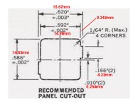
3) The Hammond enclosure we have selected (which I think is a good choice) is only 2.5" tall at the rear and that means, to be sure we have a good speaker fit, we need to move to a 2" speaker.

So the question is, how to solve all of these problems in one go ?

Firstly I would recommend we move to this 8 Ohm speaker:


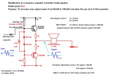
Then all we have to do is add the components on the attached diagram, shown in Red.

This modification eliminates the need for an impedance matching transformer, eliminates the DC bias on the speaker and it increases the max output power of close to a factor of 3 and allows the 8 Ohm speaker and runs the transistors well inside their ratings.

I have tested this arrangement in my lab, not with a simulation, but the real parts. In practice this will sound louder than the original system. It depends on the speaker efficiency too. Generally newer design speakers are more efficient than older ones as they tend to have much more powerful magnets.

It is just a matter of adding the parts to an additional tag strip in there, still working on that layout.
 

Attachments

  • Newampj.jpg
    Newampj.jpg
    266.1 KB · Views: 4
Firstly I would recommend we move to this 8 Ohm speaker:

Do you think this 2x3" speaker would work? I already ordered them because they were a total bargain, and were the same brand/vintage of the original: https://www.ebay.com/itm/145709281294 - they are 8ohm, I don't know the wattage though.

Also, would a small PCB work better than a tag strip? I wouldn't mind designing one, once you finalize the schematic.
 
On the Calcomp box logo thread recently, I suggested blank waterslide decal material which you colour laser print onto:
https://www.ebay.com.au/itm/293826764299
I have a few sheets of this somewhere, but sadly no access to a colour laser any more.

Updated with my results. I tried a slightly different product which worked pretty well. Normal waterslide would avoid the missing toner but either will have slightly visible label or need clear coat over it to hide. Would protect graphic better since printing below film. Not sure how it will work if your paint is textured.

https://forum.vcfed.org/index.php?threads/reproducing-calcomp-logo.1247375/#post-1374300
 
Wow that looks pretty good, I doubt anyone could tell it wasn't original. The surfaces where the decals will go on the JS-1 enclosure are not textured. I'll have to do some test runs/practicing first. So if you mess up, can you remove the label with some IPA and try again?
 
Normal waterslide would avoid the missing toner but either will have slightly visible label or need clear coat over it to hide.

I recall yet another YouTube video where the guy said you get some mailing labels, take all the labels off, print onto the backing on the side where the labels used to be and then transfer that.
 
I recall yet another YouTube video where the guy said you get some mailing labels, take all the labels off, print onto the backing on the side where the labels used to be and then transfer that.
That's exactly how I did the heat/toner transfer in post #82
 
So I wanted to give that heat toner transfer method one more try today and got some pretty excellent results this time. Slightly higher heat, made sure the label was taped down more securely, and now decal is smaller than my test yesterday (to the proper scale).. I'm going to pick up some clear spray today to see how well it holds up, I may just stick with this method! As DougM mentioned, I'm printing this onto the shiny side of a sheet of labels. Then heating the back side of the metal with a hot air rework station at about 280°C, taping a cut out section of the label paper down so it won't move. Then with sheet of paper which has been folded several times, pushing firmly and rubbing a few times to transfer the toner to the metal - this only takes a few moments. Then the label paper just peels off.

PXL_20240418_152451979.MP.jpgPXL_20240418_152506380.MP.jpg

Attached the decal sheets in PDF format, scaled to the correct sizes.
 

Attachments

  • JS-1 Decal Sheet Flipped.pdf
    116 KB · Views: 4
  • JS-1 Decal Sheet.pdf
    116.6 KB · Views: 2
Last edited:
Back
Top