• Please review our updated Terms and Rules here

Handheld PDP-8 emulation project...

alank2

Veteran Member
Joined
Aug 3, 2016
Messages
2,265
Location
USA
I am working on a PDP-8 emulator project - the idea is a small handheld PCB that is roughly 8cm x 10cm that emulates a PDP-8. I know that I could look at using something like a ARM/STM32 to really bring the power to something like this, but I love AVR's so I am going to use an AVR XMEGA 128A1U running at a baud friendly 29.4912 MHz. It doesn't have enough internal memory so I will be interfacing it to a FRAM to support 32K of 12 bit words. I like FRAM because of its similarity with magnetic core.

Instead of a binary control panel, I'm going to implement an octal control panel using 7 segment displays. I know the PDP8A had some sort of octal CP, but it looks quite unwieldy so I've designed my own. For those of you who have actually worked on these machines (I wish I had!), please let me know if you think my control panel is workable or has any flaws in operation that I am not aware of.

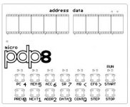
I'll attach a picture of the general look of the PCB with buttons, leds, and labels. Generally the top row will be 9 seven segment displays, 5 on the left representing the address (15bit - includes the instruction field), and 4 on the right representing the data or contents (12-bit). Under that will be a set of 7 LED's above a 7 wide 2 row keyboard. The design is that the LED above the top row of keys indicates which "view" is active, there is a view for the PC, one for the accumulator, etc. So you can see what the seven segment displays are representing by looking at the LED. If the LED is above the "PC" then the left is the program counter and the right is the opcode at that PC address. It will have a view for PC, MEMory, ACCumulator, SW (Switch Register), and MQ (Multiplier Quotient). There will also be a "view" for CFG or configuration which will allow setting breakpoints, selecting a RK05 disk image on SD card, baud rates, etc.

micropdp8.jpg

The keys act differently depending on the mode. The PREV/NEXT keys will decrement/increment the address on the left. The ADDR key will enter edit mode for the address. The DATA key will enter edit mode for the data. In edit mode, the keys then allow octal entry 0-7, and the < and > will move the digit being edited left/right. The Q will toggle quick edit mode. No quick edit mode = you type in the 4 data digits and it leaves edit mode. Quick edit mode means it moves to the next address when type type 4 digits and allows quick entering of the next 4 and so on. Otherwise you would have to hit NEXT and DATA between each of the 4 digits to go to the next address and edit it. Continue, Step, Stop, and Start are all self explanatory.

The LED above start is the RUN LED. Lit when running, out when halted.

So my first question is, does this CP replace the functionality of a binary CP? Is there anything I am missing or can improve?
 
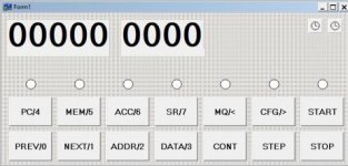
I got a basic emulator coded this weekend. Still optimizing it and it needs to go through a lot of testing, I'm sure it has a ton of things wrong. But at least I can step through instructions on the PC side now. This is merely a test application to get the code working until I can start working on the AVR. I am waiting for a DIP adapter for the 100 pin microcontroller and a dummy PCB that will allow me to easily mount the displays/leds/buttons.

pcside.jpg
 
Run the MAINDECs on your emulator - and write your own test code (but try it out on SIMH first to make sure your test code does what you think it should do).

Even then, you may still find bugs get through (as I just did the other day with my LOGISIM implementation of a PDP8/L)...

Dave
 
Used by the DEC engineers and customers to test their equipment.

They find a surprising lot of errors with emulators :)!

Dave
 
I use all the MAINDEC diagnostics to check my PDP-8m physical hardware, as well as my FPGA implementation. And SIMH when they release new PDP-8 files (there have been some bugs!).

I have collected .bin images, as well as DEC .pdf listings, disassembled .pal source files and assembled listings here: https://www.ak6dn.com/PDP-8/MAINDEC/

There are also SIMH .ini scripts to run the diagnostics.

Don
 
I got further with this tonight. The emulator is now able to successfully run my Enigma M4 assembly code for the PDP-8 so that is a start. Will move to testing the MAINDEC's once I figure out how to convert them to a binary image to pull into the emulator.

On the hardware side I finally got the microcontroller on a DIP adapter and so far it going well. Configured for the external 29.4912 MHz oscillator, USART is outputting fine at 110 to 57600 baud, and I tested the memory interface with some FRAM and SRAM which both work fast and well. Oddly, the 55ns SRAM works perfectly and the 10ns SRAM fails on the memory cell test I put it through, but I've had this problem with 10ns SRAM before. I wonder if 10ns SRAM is just too fast for breadboard use perhaps.
 
Will your FRAM based system be able to do power fail recovery? I always thought that it was amazing how it took computers 30 years to do something that computers in the 60's could do fairly easily with core...
 
The AVR has brownout detection and will go into reset below a certain voltage threshold which I will make higher than the FRAM minimum, but I had this exact problem a couple of years ago with FRAM. I was using a less wide range 4.5-5.5V and doing a read would destroy the data as there was not enough power to rewrite it properly after reading.
 
Hi,

Most excellent! Have you shared your Enigma code somewhere?

I think I have, but here it is again. This is my first and only PDP-8 assembly program, so if you see any room for improvement please point it out so I can learn! :)

Code:
/ ENIGMA M4 IMPLEMENTATION ON PDP-8
/
/ CONFIGURATION IS ALWAYS DONE THROUGH PDP-8 CONTROL PANEL
/   USE EXAMINE/DEPOSIT TO VERIFY/CHANGE ENIGMA MACHINE CONFIG
/   SEE *0020 BELOW FOR MAP OF OPTIONS
/
/ OPERATION (THERE ARE TWO MODES):
/
/   MINICOMPUTER MODE 
/     SET PROGRAM COUNTER TO 0600
/     ENTER LETTER TO ENCIPHER IN SWITCH REGISTER
/     PRESS START OR CONT TO RUN
/     RESULT WILL BE DISPLAYED IN THE ACCUMULATOR
/
/   TELETYPE MODE
/     SET PROGRAM COUNTER TO 0200
/     PRESS START OR CONT TO RUN
/     TYPE CHARACTERS ON TELETYPE AND IT WILL TYPE RESULT
/     ONLY UPPERCASE A-Z WILL BE ACCEPTED
/
/ ALL NUMBERS ARE IN OCTAL UNLESS SPECIFIED OTHERWISE
/ (DECIMAL NUMBERS WILL HAVE A D AFTER THEM LIKE 8D)
/
/ LETTER TO VALUE TABLE:
/   A-01   H-10   O-17   V-26
/   B-02   I-11   P-20   W-27
/   C-03   J-12   Q-21   X-30
/   D-04   K-13   R-22   Y-31
/   E-05   L-14   S-23   Z-32
/   F-06   M-15   T-24
/   G-07   N-16   U-25

/
/
/_PAGES_0,1,2________________________________________________________


/AUTOINCREMENTING POINTER

*0010
PTR1,   0


/ENIGMA M4 MACHINE CONFIGURATION

*0020
INDC1,  01                      /ADDRESS 0020 : 01-32 (1D-26D)
INDC2,  01                      /ADDRESS 0021 : 01-32 (1D-26D)
INDC3,  01                      /ADDRESS 0022 : 01-32 (1D-26D)
INDC4,  01                      /ADDRESS 0023 : 01-32 (1D-26D)

ROTR1,  1                       /ADDRESS 0024 : 1=BETA, 2=GAMMA
ROTR2,  01                      /ADDRESS 0025 : 01-10 (1D-8D)
ROTR3,  02                      /ADDRESS 0026 : 01-10 (1D-8D)
ROTR4,  03                      /ADDRESS 0027 : 01-10 (1D-8D)

RING1,  01                      /ADDRESS 0030 : 01-32 (1D-26D)
RING2,  01                      /ADDRESS 0031 : 01-32 (1D-26D)
RING3,  01                      /ADDRESS 0032 : 01-32 (1D-26D)
RING4,  01                      /ADDRESS 0033 : 01-32 (1D-26D)

REFL,   1                       /ADDRESS 0034 : 1=REFL B, 2=REFL C

MODE,   2                       /ADDRESS 0035 : 1=MINICOMP, 2=TELETYPE

PLUG1,  00;00                   /ADDRESS 0036 : 00 OFF, 01-32 (1D-26D)
PLUG2,  00;00                   /ADDRESS 0040 : 00 OFF, 01-32 (1D-26D)
PLUG3,  00;00                   /ADDRESS 0042 : 00 OFF, 01-32 (1D-26D)
PLUG4,  00;00                   /ADDRESS 0044 : 00 OFF, 01-32 (1D-26D)
PLUG5,  00;00                   /ADDRESS 0046 : 00 OFF, 01-32 (1D-26D)
PLUG6,  00;00                   /ADDRESS 0050 : 00 OFF, 01-32 (1D-26D)
PLUG7,  00;00                   /ADDRESS 0052 : 00 OFF, 01-32 (1D-26D)
PLUG8,  00;00                   /ADDRESS 0054 : 00 OFF, 01-32 (1D-26D)
PLUG9,  00;00                   /ADDRESS 0056 : 00 OFF, 01-32 (1D-26D)
PLUG10, 00;00                   /ADDRESS 0060 : 00 OFF, 01-32 (1D-26D)
PLUG11, 00;00                   /ADDRESS 0062 : 00 OFF, 01-32 (1D-26D)
PLUG12, 00;00                   /ADDRESS 0064 : 00 OFF, 01-32 (1D-26D)
PLUG13, 00;00                   /ADDRESS 0066 : 00 OFF, 01-32 (1D-26D)


/PAGE 0 VARIABLES AND CONSTANTS

CHAR,   0                       /HOLDS THE CHARACTER 
CINDC,  0                       /ROTOR PARAMETER
CROTR,  0                       /ROTOR PARAMETER
CRING,  0                       /ROTOR PARAMETER
C0032,  0032                    /26D


/ROTOR DATA (DO NOT MOVE)

*0107
/"EKMFLGDQVZNTOWYHXUSPAIBRCJ"; ROTOR_1M      MILITARY 1
SROTR1, 05;13;15;06;14;07;04;21;26;32;16;24;17;
        27;31;10;4030;25;23;20;01;11;02;22;03;12;

/"AJDKSIRUXBLHWTMCQGZNPYFVOE"; ROTOR_2M      MILITARY 2
SROTR2, 01;12;04;13;4023;11;22;25;30;02;14;10;27;
        24;15;03;21;07;32;16;20;31;06;26;17;05;

/"BDFHJLCPRTXVZNYEIWGAKMUSQO"; ROTOR_3M      MILITARY 3
SROTR3, 02;04;06;10;12;14;03;20;22;24;30;26;32;
        16;31;05;11;27;07;01;13;4015;25;23;21;17;

/"ESOVPZJAYQUIRHXLNFTGKDCMWB"; ROTOR_4M      MILITARY 4
SROTR4, 05;23;17;26;20;32;12;01;31;4021;25;11;22;
        10;30;14;16;06;24;07;13;04;03;15;27;02;

/"VZBRGITYUPSDNHLXAWMJQOFECK"; ROTOR_5M      MILITARY 5
SROTR5, 26;32;02;22;07;11;24;31;25;20;23;04;16;
        10;14;30;01;27;15;12;21;17;06;05;03;4013;

/"JPGVOUMFYQBENHZRDKASXLICTW"; ROTOR_6M      MILITARY 6
SROTR6, 12;20;07;26;17;25;15;06;31;21;02;05;4016;
        10;32;22;04;13;01;23;30;14;11;03;24;4027;

/"NZJHGRCXMYSWBOUFAIVLPEKQDT"; ROTOR_7M      MILITARY 7
SROTR7, 16;32;12;10;07;22;03;30;15;31;23;27;4002;
        17;25;06;01;11;26;14;20;05;13;21;04;4024;

/"FKQHTLXOCBJSPDZRAMEWNIUYGV"; ROTOR_8M      MILITARY 8
SROTR8, 06;13;21;10;24;14;30;17;03;02;12;23;4020;
        04;32;22;01;15;05;27;16;11;25;31;07;4026;

/"LEYJVCNIXWPBQMDRTAKZGFUHOS"; ROTOR_BETA    MILITARY M4 BETA
SROTB, 14;05;31;12;26;03;16;11;30;27;20;02;21;
       15;04;22;24;01;13;32;07;06;25;10;17;23;

/"FSOKANUERHMBTIYCWLQPZXVGJD"; ROTOR_GAMMA   MILITARY M4 GAMMA
SROTG, 06;23;17;13;01;16;25;05;22;10;15;02;24;
       11;31;03;27;14;21;20;32;30;26;07;12;04;

/"ENKQAUYWJICOPBLMDXZVFTHRGS", ROTOR_REFL4B  MILITARY M4 B REFLECTOR
SREFLB, 05;16;13;21;01;25;31;27;12;11;03;17;20;
        02;14;15;04;30;32;26;06;24;10;22;07;23;

/"RDOBJNTKVEHMLFCWZAXGYIPSUQ"; ROTOR_REFL4C  MILITARY M4 C REFLECTOR
SREFLC, 22;04;17;02;12;16;24;13;26;05;10;15;14;
        06;03;27;32;01;30;07;31;11;20;23;25;21;

*0577
STOP,   HLT                     /FOR MINICOMP MODE THIS HALTS LEAVING
                                /USER AT ENTRY POINT 0600
/
/
/_PAGE_3_____________________________________________________________

*0600
ENTRY,  CLA CLL                 /GET MODE
        TAD MODE
        TAD C7777               /SUBTRACT 1
        SNA                     /SKIP NEXT INSTRUCTION IF NON ZERO
        JMP MINI                /JMP TO MINICOMP MODE

TELE,   KSF                     /SKIP IF READER FLAG SET
        JMP .-1                 /WAIT FOR KEY
        KRB                     /KBD->ACC, CLEAR FLAG
        DCA CHAR                /STORE CHAR SO WE CAN TEST IT
        TAD CHAR                /ALLOW ONLY A-Z (65-90)
        TAD C7677               /SUBTRACT 65
        SPA CLA                 /SKIP ON PLUS OR ZERO, CLEAR ACC
        JMP TELE                /LESS THAN 65, SKIP
        TAD CHAR                /RESTORE CHAR
        TAD C7645               /SUBTRACT 91
        SMA CLA                 /SKIP ON MINUS, CLEAR ACC
        JMP TELE                /MORE THAN 90, SKIP
        CLA CLL                 /IT IS VALID A-Z, RESTORE CHAR
        TAD CHAR
        TAD C7700               /SUBTRACT 64 SO A=1 (1 BIASED)
        JMS CIPHER              /CALL CIPHER
        TAD C0100               /ADD 64 SO a=65 (65 BIASED)
        TSF                     /SKIP IF PRINT FLAG SET
        JMP .-1                 /LOOP UNTIL READY
        TLS                     /PRINT
        JMP TELE                /WAIT FOR NEXT KEY

MINI,   LAS                     /LOAD AC WITH SWITCH REGISTER
        JMS CIPHER              /CALL CIPHER
        JMP I PSTOP             /JMP TO STOP FOR HALT


CIPHER, 0                       /SUBROUTINE RETURN ADDRESS STORE HERE
        DCA CHAR                /STORE ACC IN CHAR

PST,    JMS I PSTEP             /CALL STEP TO STEP THE ROTORS

PL1,    JMS I PSPLUG            /CALL PLUGBOARD TO SWAP THE LETTERS

F4,     TAD INDC4               /SETUP AND CALL FORWARD ROTOR FOR 4
        DCA CINDC
        TAD ROTR4
        DCA CROTR
        TAD RING4
        DCA CRING
        JMS I PFROTOR

F3,     TAD INDC3               /SETUP AND CALL FORWARD ROTOR FOR 3
        DCA CINDC
        TAD ROTR3
        DCA CROTR
        TAD RING3
        DCA CRING
        JMS I PFROTOR

F2,     TAD INDC2               /SETUP AND CALL FORWARD ROTOR FOR 2
        DCA CINDC
        TAD ROTR2
        DCA CROTR
        TAD RING2
        DCA CRING
        JMS I PFROTOR

F1,     TAD INDC1               /SETUP AND CALL FORWARD ROTOR FOR 1
        DCA CINDC
        TAD ROTR1
        TAD C0010               /BETA/GAMMA ACTUALLY AT 9 AND 10 (+8)
        DCA CROTR
        TAD RING1
        DCA CRING
        JMS I PFROTOR

FREFL,  CLA CLL IAC             /LOAD ACC WITH 1
        DCA CINDC
        TAD REFL
        TAD C0012               /REFLECTOR ACTUALLY AT 11 AND 12 (+10)
        DCA CROTR
        CLA CLL IAC             /LOAD ACC WITH 1
        DCA CRING
        JMS I PFROTOR           /CALL REFLECTOR

R1,     TAD INDC1               /SETUP AND CALL REVERSE ROTOR FOR 1
        DCA CINDC
        TAD ROTR1
        TAD C0010               /BETA/GAMMA ACTUALLY AT 9 AND 10 (+8)
        DCA CROTR
        TAD RING1
        DCA CRING
        JMS I PRROTOR

R2,     TAD INDC2              /SETUP AND CALL REVERSE ROTOR FOR 2
        DCA CINDC
        TAD ROTR2
        DCA CROTR
        TAD RING2
        DCA CRING
        JMS I PRROTOR

R3,     TAD INDC3               /SETUP AND CALL REVERSE ROTOR FOR 3
        DCA CINDC
        TAD ROTR3
        DCA CROTR
        TAD RING3
        DCA CRING
        JMS I PRROTOR

R4,     TAD INDC4               /SETUP AND CALL REVERSE ROTOR FOR 4
        DCA CINDC
        TAD ROTR4
        DCA CROTR
        TAD RING4
        DCA CRING
        JMS I PRROTOR

PL2,    JMS I PSPLUG            /CALL PLUGBOARD TO SWAP THE LETTERS

STR1,   CLA CLL                 /LOAD CHAR INTO ACC TO RETURN
        TAD CHAR
        JMP I CIPHER            /RETURN FROM SUBROUTINE


/THIS PAGE VARIABLES AND CONSTANTS

C0010,  0010                    /8D
C0012,  0012                    /10D
C0100,  0100                    /64D
C7700,  7700                    /-64D
C7645,  7645                    /-91D
C7677,  7677                    /-65D
C7777,  7777                    /-1D
PSTOP,  STOP
PSTEP,  STEP
PSPLUG, SPLUG
PFROTOR,FROTOR
PRROTOR,RROTOR

/
/
/_PAGE_4_____________________________________________________________

*1000
SPLUG,  0                       /SUBROUTINE RETURN ADDRESS STORED HERE
        CLA CLL
        TAD PPLUG1              /RESET PLUGBOARD POINTER PTR1
        DCA PTR1
        TAD COUNT               /SETUP COUNT AND INDEX FOR LOOP
        CIA                     /NEGATE (INDEX COUNTS UP TO 0)
        DCA INDEX1

LOOP,   TAD I PTR1              /CHECK PLUGBOARD PAIR FIRST VALUE
        SNA                     /SKIP NEXT INSTRUCTION IF NON ZERO
        JMP DSBL                /THIS PLUGBOARD PAIR IS DISABLED
        CIA                     /NOT DISABLED, CONTINUE COMPARING TO OUR CHAR
        TAD CHAR                /ADD CHARACTER, IF IT MATCHES ACC WILL BE 0
        SNA                     /SKIP NEXT INSTRUCTION IF NON ZERO
        JMP MATCH1              /MATCH FIRST VALUE IN PAIR
        CLA CLL                 /NOT ZERO, NO MATCH, CLEAR ACC
        TAD I PTR1              /GET SECOND PAIR VALUE
        CIA                     /COMPARE IT TO OUR CHARACTER
        TAD CHAR       
        SNA                     /SKIP NEXT INSTRUCTION IF NON ZERO
        JMP MATCH2              /IT IS ZERO, MATCH SECOND VALUE IN PAIR

LOOP2,  CLA CLL                 /NO MATCH THIS PAIR
        ISZ INDEX1
        JMP LOOP
        JMP I SPLUG             /RETURN FROM SUBROUTINE

DSBL,   TAD I PTR1              /THIS PAIR IS DISABLED, SKIP OTHER HALF
        JMP LOOP2

MATCH1, TAD I PTR1              /FIRST WORD MATCHES, OBTAIN OTHER HALF
        DCA CHAR
        JMP I SPLUG             /RETURN FROM SUBROUTINE

MATCH2, CLA CLL CMA RAL         /SECOND WORD MATCHES, ACC=7776 (-2)
        TAD PTR1                /ADD PTR1 TO ACC
        DCA PTR1                /DEPOSIT PTR1-2 TO GET FIRST VALUE
        JMP MATCH1


STEP,   0                       /SUBROUTINE RETURN ADDRESS STORED HERE
        CLA CLL                 /IS ROTOR3 IN NOTCH?
        TAD ROTR3
        JMS I PRPTR             /SET ROTOR POINTER TO CORRECT ROTOR
        TAD INDC3
        DCA TEMP1
        TAD I TEMP1
        AND C4000               /KEEP ONLY NOTCH BIT
        SZA                     /SKIP ON ZERO
        JMP STEP3               /YES - 3 RIGHT ROTORS MOVE
        TAD ROTR4               /IS ROTOR4 IN NOTCH? 
        JMS I PRPTR             /SET ROTOR POINTER TO CORRECT ROTOR
        TAD INDC4
        DCA TEMP1
        TAD I TEMP1
        AND C4000               /KEEP ONLY NOTCH BIT
        SZA                     /SKIP ON ZERO
        JMP STEP2               /YES - 2 RIGHT ROTORS MOVE
        JMP STEP1               /NO - 1 RIGHT ROTOR MOVES

STEP3,  CLA CLL                 /STEP ROTOR 2
        TAD INDC2
        IAC
        JMS I PRBACK            /IF OVERFLOW ROLL IT BACK TO 1
        DCA INDC2
                                /INTENTIONAL LACK OF JMP STEPS REMAINING

STEP2,  CLA CLL                 /STEP ROTOR 3
        TAD INDC3
        IAC
        JMS I PRBACK            /IF OVERFLOW ROLL IT BACK TO 1
        DCA INDC3
                                /INTENTIONAL LACK OF JMP STEPS REMAINING

STEP1,  CLA CLL                 /STEP ROTOR 4
        TAD INDC4
        IAC
        JMS I PRBACK            /IF OVERFLOW ROLL IT BACK TO 1
        DCA INDC4
                                /INTENTIONAL LACK OF JMP STEPS REMAINING

STEP0,  JMP I STEP              /RETURN FROM SUBROUTINE


/THIS PAGE VARIABLES AND CONSTANTS

C4000,  4000                    /NOTCH BIT IN ROTORS
COUNT,  15                      /13D
INDEX1, 0                       /0D
PPLUG1, PLUG1-1                 /POINTER TO WORD BEFORE PLUGBOARD
TEMP1,  0
PRPTR,  RPTR
PRBACK, RBACK

/
/
/_PAGE_5_____________________________________________________________

*1200
FROTOR, 0
        TAD CRING               /CINDC+26-CRING+CHAR
        CIA
        TAD CINDC
        TAD C0032
        TAD CHAR
        JMS RBACK
        DCA TEMP2
        TAD CROTR
        JMS RPTR                /SET ROTOR POINTER TO CORRECT ROTOR
        TAD TEMP2
        DCA TEMP2
        TAD I TEMP2
        AND C0077
        CIA
        TAD CINDC
        CIA
        TAD CRING
        TAD C0032
        JMS RBACK
        DCA CHAR
        JMP I FROTOR            /RETURN FROM SUBROUTINE


RROTOR, 0
        DCA TEMP3               /STORE 0
        TAD C0032
        CIA                     /NEGATE (INDEX COUNTS UP TO 0)
        DCA INDEX2

LOOP3,  ISZ TEMP3
        TAD CRING               /CINDC+26-CRING+CHAR
        CIA
        TAD CINDC
        TAD C0032
        TAD TEMP3
        JMS RBACK
        DCA TEMP2
        TAD CROTR
        JMS RPTR                /SET ROTOR POINTER TO CORRECT ROTOR
        TAD TEMP2
        DCA TEMP2
        TAD I TEMP2
        AND C0077
        CIA
        TAD CINDC
        CIA
        TAD CRING
        TAD C0032
        JMS RBACK
        CIA                     /COMPARE BY NEGATING
        TAD CHAR                /ADD CHARACTER, IF IT MATCHES ACC WILL BE 0
        SNA                     /SKIP NEXT INSTRUCTION IF NON ZERO
        JMP MATCH3              /MATCH FIRST VALUE IN PAIR
        ISZ INDEX2
        CLA CLL
        JMP LOOP3

MATCH3, TAD TEMP3
        DCA CHAR
        JMP I RROTOR            /RETURN FROM SUBROUTINE


RPTR,   0                       /CALCULATE ROTOR POINTER 
        CIA
        DCA TEMP4

PTRLP,  TAD C0032
        ISZ TEMP4
        JMP PTRLP
        TAD C0054
        JMP I RPTR              /RETURN FROM SUBROUTINE


RBACK,  0                       /IF ACC>32, SUBTRACT 32 UNTIL IT IS

RBACK2, DCA TEMP4
        TAD TEMP4
        TAD C7746
        SMA SZA
        JMP RBACK2
        CLA CLL
        TAD TEMP4
        JMP I RBACK             /RETURN FROM SUBROUTINE


/THIS PAGE VARIABLES AND CONSTANTS

C0054,  0054                    /CONSTANT TO GENERATE ROTOR PTR
C0077,  0077                    /63D
C7746,  7746                    /-26D
TEMP4,  0
INDEX2, 0
TEMP2,  0
TEMP3,  0

$ENTRY
 
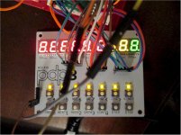
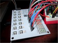
My test board to see how well the displays/leds/keyboard works arrived and works great. It is only a test board with only the displays/leds/keys and the necessary things to drive them.

The 6 pin headers will obviously not be on the real thing. The displays on the right are also testing various colors (red, orange, yellow, green). You can see I burned the face of the orange one with the iron by accident!!!

pdp8_1.jpg

pdp8_2.jpg
 
It's a shame that calculator "bubble" LED displays have become so rare and expensive.

This is a very interesting project. Someone on the PiDP8 Google group (perhaps you?) had a PDP-8, 4 or 8K of RAM (not sure), and a tape based DEC OS running on a single AVR chip a while ago.

I've made several emulators using the ESP8266 for the 8008 and 8080. my better efforts were the 8080 CP/M system with a 64K SPI SRAM and wireless Telnet or RS-232, and an 8008 emulator with bit-banged NTSC video and PS/2 keyboard, later with an added paper tape reader. I've been tempted to rip out the guts out of these projects and stick a PDP8 emulator in with OS/8 in the flash. What's stopped me is that I have a wire-wrapped (Spare Time Gizmos) SBC6120 8/e and a PiDP8, and I still haven't learned everything about THEM yet.


https://hackaday.io/project/161404
https://hackaday.io/project/26262
 
Thanks; that must be someone else with the AVR PDP8, this is my first go at it.

I like the bubble displays too - I did a breadboard meter with them years ago:

https://www.youtube.com/watch?v=0YUA0QKOs0E

Cool hackaday projects - I've got a CP/M project I keep starting and stopping so someday hopefully I'll get it finished!
 
My initial test (my enigma code modified to not stop, but keep running endlessly) was around 108K instructions per second. I think the PDP8 was 0.333 MIPS or 333K instructions per second so I was a bit concerned that the AVR wouldn't be fast enough, but after optimizing it again and again and seeing what gcc produces in ASM, I got it up to 308K now. Probably if it was written in ASM it would be faster, but I am not familiar with AVR ASM right now. I can move from 29.4912 MHz to a 32 MHz and make up the difference between 308K/s and 333K/s, but who knows the actual speed when I add/implement more stuff for the EAE, etc. It doesn't have to be right on, but at least in the ballpark so it isn't slow.
 
Back
Top