• Please review our updated Terms and Rules here

386/486DLC Can't enter bios/wait screen/out of range? Huh?

joebelter

Experienced Member
Joined
Jan 22, 2025
Messages
59
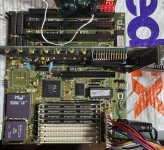
Hello, I hope someone can help! I've scoured the net looking for my board but can't find the company, so It's probably one of those "unknowns."
It had Varta damage when I got it, but I got it cleaned up and replaced a few caps that were Varta damaged. On first boot I kept getting the three beep memory errors.
After inspection, I noticed tha I had some issues with a couple of pins in the sim sockets, but got those straightened out - and no more beeping.
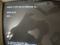
Now when I apply power I get the video card screen, then the initial Bios screen telling me to press del to enter the bios.
Pressing del does nothing - in fact, on two different LCD monitors I get a message that says "out of range" (I think it's related to the 720x400).
I've tried a Cirrus VGA card and it does the same thing. I've tried a CRT VGA monitor and it doesn't help. Used an AT keyboard and a PS/2 with AT adapter.
Tried removing the "display" jumper" and resetting the bios as well by shorting the pins (correct?)
I've tried just about everything I can think of... The Analyzer card says "8382" and no beeping.
If it were in a crashed state would the analyzer card do anything different?
Any ideas?? Things to test?
One odd thing - one of the jumpers has a setting for 66M or 80M. Don't know what that's for. Can't imagine it's mhz??
Very much appreciate your help here!
Joe
 

Attachments

  • 486dlc.jpg
    486dlc.jpg
    164.7 KB · Views: 16
  • 486dlc wait.jpg
    486dlc wait.jpg
    42.8 KB · Views: 17
Pressing del does nothing - in fact, on two different LCD monitors I get a message that says "out of range" (I think it's related to the 720x400).
Both 640x400 and 720x400 use identical signal timing, which should be compatible with all LCD monitors. That's not the problem.

If pressing DEL does not do anything, you might want to check if the keyboard works at all. Battery damage tends to hit the keyboard controller and surrounding areas, so you may have additional trace damage to fix first.

I had a somewhat similar board where trace damage caused the main clock to be unstable. The system did boot, but it was not stable and benchmark numbers were wrong. An unstable clock could also throw off the video timing produced by the video card, causing the "out of range".

One odd thing - one of the jumpers has a setting for 66M or 80M. Don't know what that's for. Can't imagine it's mhz??
A 386/486DLC processor is fed with twice its operating frequency, so the jumper switches between 33 MHz and 40 MHz operation.
 
The pictures are low quality JPEG so it's hard to tell, but it looks like there's more trace damage that wasn't repaired.

You may also want to check VIAs in that area, battery corrosion often destroys them.
 
Here's my keyboard bios with a blob of solder on top? It's down on the opposite side of the board from where the Varta was.
Is the solder there for a reason?
Thanks for the replies!
Joe
 

Attachments

  • 486dlc keyboard.jpg
    486dlc keyboard.jpg
    93.2 KB · Views: 12
  • 486dlc keyboard 2.jpg
    486dlc keyboard 2.jpg
    46.3 KB · Views: 12
Yep. just noticed that! I fixed it and got further - now I get to CMOS settings not set Press F1 to continue,
Tried two both AT and adapted PS/2 and no go.
Joe
 
Yep. just noticed that! I fixed it and got further - now I get to CMOS settings not set Press F1 to continue,
Tried two both AT and adapted PS/2 and no go.
I agree with Svenska. There could be one or more damaged tracks (relating to keyboard functionality) that you have yet to discover.
 
Looking through the microscope and can't see anything obvious... killer! So close!!! Would be my FIRST VICTORY!
Check the resistors? Or other components close to the board?
Could the keyboard bios be faulty? If so can I replace it?
Joe
 
I checked and found no continuity between the keyboard socket pinouts and the keyboard controller chip.??
 
Further testing revealed that I did get continuity between the following pins:
Pin 3 - Pin 1 on Keyboard controller
Pin 4- Pin 26,40 on the Keyboard controller
Pin 5- Pin 33 on the Keyboard controller. I couldn't find a "1" on the controller so assumed "U1" on the upper left of the chip where the u shaped cutout is. Check my picture above for the chip.
I tried looking this up, but makes no sense.
One thing - I DO get the three green lights on the keyboard flashing when I first boot...
 
Last edited:
Instead of continuity, use resistance mode. "Continuity" varies between multimeters, I've seen it range from 0-50 ohms. A track shouldn't be more than an ohm, if it is, it will cause issues.

You also need to check for resistance between tracks to see if there are any stray current paths.

If you don't find anything, you'll have to start pulling connectors and ICs to look for hidden damage.
 
Ok, I'm stupid. I admit it!
I don't know what the HECK I was doing/thinking...
But I got out a working 386sx and did a comparison pin for pin between the keyboard connector and the keyboard programmer.
EVERYTHING was exactly the SAME except the data pin to pin 38 on the Keyboard programmer. No continuity there.
I discovered that TINY trace was missing between the back of the keyboard socket and where the trace is on the board. I put a wire bodge wire there and BANG - continuity!!
I then checked the two boards against each other for continuity to the PSU connector on the board. They are identical!
My heart pounded with excitement as I booted the board...
but alas... NO CHANGE!
Noooooooooooo!
What now?

Joe
 
Instead of continuity, use resistance mode. "Continuity" varies between multimeters, I've seen it range from 0-50 ohms. A track shouldn't be more than an ohm, if it is, it will cause issues.

You also need to check for resistance between tracks to see if there are any stray current paths.

If you don't find anything, you'll have to start pulling connectors and ICs to look for hidden damage.
Hmmmm... How do I do that? I'm new to this game and learning slooooowly (obviously)
I can certainly start pulling stuff out... One thing I always wonder is the damage OXIDATION has on connections. Half the board has solder joints that would have to be reflowed, but it's really a pain to do when a solder joint is oxidized. It's like you have to scrape all the crud off first, and it's TEDIOUS. Is it really necessary?
 
Hmmmm... How do I do that? I'm new to this game and learning slooooowly (obviously)

I don't know what multimeter you have, but instead of using diode mode, use ohms mode. If you don't have an auto ranging meter, set it to the lowest ohms scale, usually something like 200 ohms. That will give you a measurement from 0-200 ohms. If you do have an auto ranging meter, you still may want to use manual range mode so you don't have to wait for the meter to calculate the range before giving you a reading. Just remember that your probe leads also have a resistance, so you should measure that first to get a reading by touching the probe leads together. You can subtract that number from the reading you get when probing the board.

I can certainly start pulling stuff out... One thing I always wonder is the damage OXIDATION has on connections. Half the board has solder joints that would have to be reflowed, but it's really a pain to do when a solder joint is oxidized. It's like you have to scrape all the crud off first, and it's TEDIOUS. Is it really necessary?

Oxidized =! corroded. All solder joints will eventually oxidize to some degree from the base metal reacting with the oxygen in the air. If the connection is a dull grey color, it is most likely fine. If the connection has white fluff, green, blue, black or dark brown in it, then that's a problem. It's also a problem if the solder joint has cracks, is detached from the board or has a ring in the joint, which usually indicates heat stress or excessive mechanical movement.

I would recommend a syringe of good flux to clean corroded connections. Apply the flux and reheat the joint, don't be afraid to scrub the joint with the tip while covered in flux to break up the oxidation.
 
Back
Top