• Please review our updated Terms and Rules here

74ls134 replacement?

Ok.

With the CPU still removed, can you scope the following pins please:

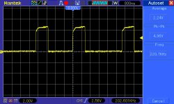
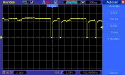
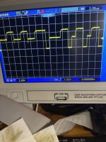
Z64 pin 1 (VID*). I am expecting this to be permanently HIGH.

Z63 pin 3 (VWR*). I am expecting this to be permanently HIGH.

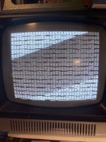
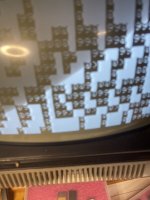
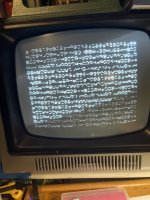
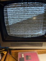
My current train of thought - assuming the screen display that you have with the CPU removed is nice and static - is that the Z80 CPU is affecting the display (possibly through corruption or 'bleed-through' of the data bus into the vide RAMs).

Let me see if we can inhibit the VID* signal with the CPU in circuit and see if that stabilises the display.

Dave
 
Ah,

So there is a convenient test we can do...

1720530195328.png

With the CPU installed, power up the machine and observe the 'corrupt' screen.

Using a low-valued resistor (say 100 to 220 Ohms) connect the CPU pin 25 (/BUSRQ) to 0V using the resistor. Note that there is a connector (pin 23) identified as TEST* available.

This TEST/ signal will cause the CPU to stop what it is doing. When you install the resistor, does the display return to 'normal' - albeit with potentially junk characters on the screen. However, the display should (hopefully) look the same as our power-up condition without the CPU. The ASCII characters should be well-formed again...

We are using the low-value resistor just in case you install the resistor on the wrong point. This will limit the current and prevent any damage to the logic.

You are correct. Z52 should be identified as 74LS04 instead of 74LS34.

Dave
 
With the character generator chip removed, you should have all boxes on the screen which is happening, but there’s also garbage in the rows. The chips in z10 and z11 are 74ls166’s. Is that what you asked me?
 

Attachments

  • image.jpg
    image.jpg
    2.5 MB · Views: 5
This is what I get when I shunt that pen 25 does stop the oscillation
 

Attachments

  • image.jpg
    image.jpg
    1.4 MB · Views: 5
That is interesting...

So the CPU is affecting the display...

I think what you are seeing when you removed the character generator is the solid block of white (from the character generator / text parallel to serial shift register) mixed with random illuminated bits (from the graphics parallel to serial shift register).

If you look at the screen, I can't see any black pixels where the white pixels are from the solid text block.

All of the white extraneous pixels occur where black pixels should be.

I am asking which IC devices ON THE PCB are in sockets.

I have a meeting I have to attend now...

Dave
 
I assume Z63 (video RAM data bit 7) is in an IC socket?

With the Z80 running, can you use your oscilloscope to observe what is present on the following:

Z26 pin 6.
Z26 pin 4.

On the assumption that the display should be entirely text characters, I am assuming that pin 4 should be LOW and pin 6 should be HIGH.

Dave
 
z63 is socketed
Pic 1 is z26 pin 4
Pic 2 is z26 pin 6
 

Attachments

  • pic_90_1.jpg
    pic_90_1.jpg
    112.4 KB · Views: 2
  • pic_90_2.jpg
    pic_90_2.jpg
    117.8 KB · Views: 2
There is activity, so this implies that the graphics part of the video circuitry is being activated.

I am going out this evening, so we can continue this tomorrow if that is OK.

Dave
 
Been trying to figure out what’s causing the graphics to be on all the time. The only thing I could find that doesn’t look right is pin seven on z8
 

Attachments

  • image.jpg
    image.jpg
    1.9 MB · Views: 1
Sorry, I have got buried in a rather long meeting at the moment...

I would remove the graphics parallel to serial shift register Z11 (74LS166) if it is in an IC socket.

The screen should go all white - as the output pin (13) is now floating HIGH.

Use your low-value resistor to connect Z11 pin 13 to 0V.

This should completely disable the graphics signal into the video mixer and we should be able to see on the screen what is produced by the text parallel to serial shift register (Z10) alone.

Dave
 
Z8 pin 7 does look strange, but the data from Z8 feeds into into Z11 (graphics parallel to serial shift register) and Z11 should not be activated (Z11 pin 15 should remain HIGH).

But, from our previous probing, Z11 is being activated (for some reason) and messing up the video signal.

Now, it is possible that there are two (2) concurrent faults, but I wouldn't go replacing Z8 until we fix the problem we are currently working on - and then we can see if there is another fault and (if so) we can work on that.

Dave
Z8 already changed and in socket
 
So, we have got rid of all the 'white' lines and replaced them with 'black' lines (i.e. the data is still 'effectively' being switched from the character side to the graphics side - but we have 'nobbled' the graphics side by removing the device and installing the resistor).

I am currently thinking that there is either a problem with video RAM data bit 7, or with the video RAM circuitry in general.

I am thinking about removing the video RAM for D7, and using the resistor again to set the data output to 0V.

Then we should be able to see what is going on with the other video RAM data bits.

Dave
 
Dad, a bit seven output pool to ground through resistor. This is what I get.
 

Attachments

  • image.jpg
    image.jpg
    2.1 MB · Views: 11
Does that look like a 'corrupt' @9@9@9... display to you, or is it just wishful thinking on my part?

The fault does look like more than video RAM data bit 7 though.

The next thing (in my book) would be to disable the VID* signal (i.e. prevent the CPU from writing to the display).

Dave
 
Back
Top