• Please review our updated Terms and Rules here

A-trend ATC-1425A - anyone has it?

nixxon

Member
Joined
Jul 2, 2007
Messages
11
Location
Bucharest, Romania
I got this board a few days ago and although it looks almost new, it seems someone unsoldered some parts from it... As it stands now, it is missing 6 capacitors (2 electrolytics, 4 smd) and 8 smd resistors. To have any chance of repairing it I need some close-ups of the board, and I haven't been able to find them on the net. If someone has this board, please share some photos of it. I highlighted on the attached photo the areas that are of interest to me. Many thanks!

https://imgur.com/a/inaALYj
 
You have more to worry about than just missing passive components.

The board is missing the i8042 keyboard controller and the BIOS chip. Without these, the board won't function. The i8042 is a microcontroller with internal ROM, so unless you find one from this exact board or one very similar to it, it won't work. The same goes for the BIOS chip, you'll have to find a 27c010 EPROM and write the BIOS image to it and hope it works.

The capacitors can be worked out by what's around them. All of the electrolytic caps are the same, so just get more of those. The SMD ceramics are likely decoupling capacitors, just measure ones nearby that look the same and replace with the same value. The resistors are a bit more difficult, but can generally be worked out by what's around them. But fixing any of this is pointless unless you can get the i8042 and BIOS chip.
 
Thank you for your reply.

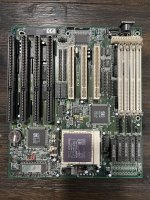
I have both the BIOS chip and the keyboard controller, only after I photoshopped the image I noticed they are missing and didn't want to start over. The reason for that - I give each board a good scrub when I receive it, and usually remove all that is removable.

After studying some datasheets and comparing to other boards with the same SiS chipset, I managed to find out/guess the values for most of the missing parts, but there are still a few unknowns and I feel these are enough for the board to mis-behave:

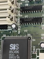
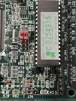
- On the ATC-1425A there is a resistor (R68, missing/removed) that pulls up pin 126 (DIRTY/MA11/PREQ3#) of the SiS northbridge. On all my other SiS 496/497 boards, this pin only connects to one input of an 74F244 buffer, but on the A-trend it also connects to this pull-up resistor.
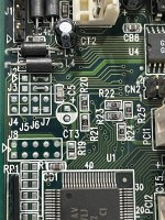
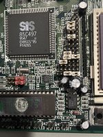
- C30 and C31, two capacitors that are used as snubbers (I guess?) between northbridge pin 31 (ACLK) and GND, respectively pin 81 (CPUCLK) and GND. They are unmarked on my other boards, and I'm guessing they are in the low pF range so I couldn't measure them anyway.
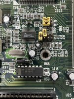
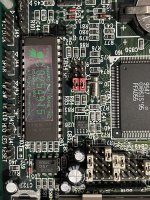
- A pair of resistors (R84, R85) that are part of the VRM, near the voltage selection jumpers. Without them, one of the settings becomes unavailable, but I still have two other choices (besides +5v) for the CPU voltage, and if I get the board working I could work out their values by trial and error / using some variable resistors in their place until I get the desired voltage.

Other missing parts are already found out / guessed or their values are not so critical. I'm slowly giving up hope that someone will provide the photos, this board seems to be not so common and I've already PM'ed three users on different forums but they either don't respond or don't visit the forums anymore, so if anyone has any suggestion regarding my missing values...
 
There are pictures of this board on the net, but none are high enough resolution to be of any use.

You should just start putting components on which you think might work, no sense in waiting forever for pictures that may or may not help.
 
I got this board a few days ago and although it looks almost new, it seems someone unsoldered some parts from it... As it stands now, it is missing 6 capacitors (2 electrolytics, 4 smd) and 8 smd resistors. To have any chance of repairing it I need some close-ups of the board, and I haven't been able to find them on the net. If someone has this board, please share some photos of it. I highlighted on the attached photo the areas that are of interest to me. Many thanks!


I know it has been a long time but do you still need pictures? I have a working motherboard that I can take very high resolution pictures for you :)
 
Gotta love these forums :)
I still have the board. Managed to get it running shortly after my previous post. Couldn't match the values of the VRM resistors so I installed a multiturn trimpot and instead of a few discrete steps I can dial-in any voltage I want, found out that literally any Am5x86-133 could do 160MHz given enough juice (3.7 to 4 volts).
That being said, having the pictures would be nice. Thank you in advance!
 
Ok, I'll attach several photos, let me know if you want me to zoom in to a specific spot :)

It might take me a while because I'm a new user and a Mod has to approve every one of my posts :)
 

Attachments

  • IMG_9210.jpg
    IMG_9210.jpg
    5.1 MB · Views: 5
Gotta love these forums :)
I still have the board. Managed to get it running shortly after my previous post. Couldn't match the values of the VRM resistors so I installed a multiturn trimpot and instead of a few discrete steps I can dial-in any voltage I want, found out that literally any Am5x86-133 could do 160MHz given enough juice (3.7 to 4 volts).
That being said, having the pictures would be nice. Thank you in advance!

Capacitors C14 and CT18 are both 100uf 16v and CT26 is 470uf 16v.
 

Attachments

  • unnamed (1).jpg
    unnamed (1).jpg
    1.3 MB · Views: 2
Gotta love these forums :)
I still have the board. Managed to get it running shortly after my previous post. Couldn't match the values of the VRM resistors so I installed a multiturn trimpot and instead of a few discrete steps I can dial-in any voltage I want, found out that literally any Am5x86-133 could do 160MHz given enough juice (3.7 to 4 volts).
That being said, having the pictures would be nice. Thank you in advance!

R68 says 102
 

Attachments

  • unnamed (2).jpg
    unnamed (2).jpg
    1.2 MB · Views: 2
Gotta love these forums :)
I still have the board. Managed to get it running shortly after my previous post. Couldn't match the values of the VRM resistors so I installed a multiturn trimpot and instead of a few discrete steps I can dial-in any voltage I want, found out that literally any Am5x86-133 could do 160MHz given enough juice (3.7 to 4 volts).
That being said, having the pictures would be nice. Thank you in advance!
 

Attachments

  • IMG_9231.jpg
    IMG_9231.jpg
    1.5 MB · Views: 4
Thank you, much appreciated! If it's possible, one more picture, area between BIOS chip and southbridge (bottom-right rectangle on my pic). If I ever decide to restore the original VRM...
 
Thank you, much appreciated! If it's possible, one more picture, area between BIOS chip and southbridge (bottom-right rectangle on my pic). If I ever decide to restore the original VRM...
 

Attachments

  • IMG_9232.jpg
    IMG_9232.jpg
    1.6 MB · Views: 1
Thank you, much appreciated! If it's possible, one more picture, area between BIOS chip and southbridge (bottom-right rectangle on my pic). If I ever decide to restore the original VRM...
 

Attachments

  • IMG_9261.jpg
    IMG_9261.jpg
    2.3 MB · Views: 1
Thank you, much appreciated! If it's possible, one more picture, area between BIOS chip and southbridge (bottom-right rectangle on my pic). If I ever decide to restore the original VRM...
 

Attachments

  • IMG_9263.jpg
    IMG_9263.jpg
    1.8 MB · Views: 1
Thank you, much appreciated! If it's possible, one more picture, area between BIOS chip and southbridge (bottom-right rectangle on my pic). If I ever decide to restore the original VRM...
 

Attachments

  • IMG_9264.jpg
    IMG_9264.jpg
    1.9 MB · Views: 2
Thank you, much appreciated! If it's possible, one more picture, area between BIOS chip and southbridge (bottom-right rectangle on my pic). If I ever decide to restore the original VRM...

Hopefully that helps :)
I tried to get all pictures as clear as possible :)
Let me know if you need anymore :)
 
Back
Top